Elements of the brake system with ABS
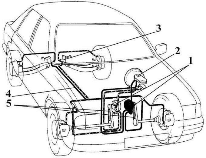
1 - modulators; 2 – the main brake cylinder; 3 - pressure regulator; 4 – brake pipes; 5 - toothed belts
ABS modulator
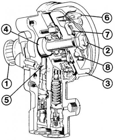
1 - pulley; 2 - shaft; 3 - flywheel; 4 - eccentric; 5 - pump plunger; 6 - low speed stop; 7 - friction clutch; 8 - ball stopper
ABS drive
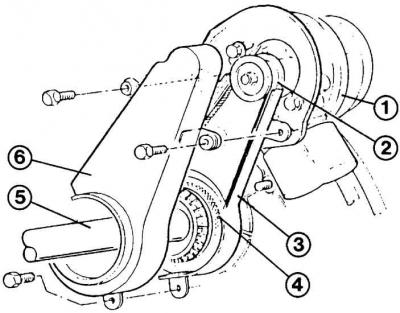
1 - control module; 2 - pulley; 3 – a gear belt of a drive; 4 - drive pulley; 5 - drive shaft; 6 – a cover of a gear belt
Anti-lock braking system
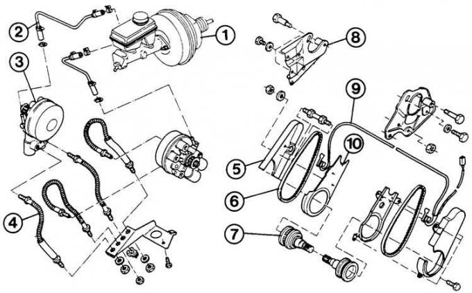
1 - vacuum brake booster with the main brake cylinder; 2 - return pipeline; 3 - regulator; 4 – brake pipes; 5 - outer belt cover; 6 - toothed belt; 7 – drive shaft pulley; 8 – regulator fastening; 9 - electric belt tension drive; 10 - inner belt cover
The wheel speed control system includes two modulators driven by drive shafts through a toothed belt. In vehicles equipped with an anti-lock braking system, a brake regulator is installed that reacts to the loading of the vehicle.
The anti-lock braking system works as follows. During heavy braking, if the deceleration of the front wheel exceeds a certain value, the tendency of the wheel to block is transmitted through the toothed belt to the modulator connected to it. At this moment, the flywheel is activated in the modulator, which controls the brake system valves, which reduce or restore the brake fluid pressure in the wheel cylinder.
Over time, the flywheel speed drops and, since at the same time the shut-off valve interrupts the transmission of pressure from the brake master cylinder to the brake, the braking intensity decreases. As a result, the front wheel speeds up again to a decreasing flywheel speed. Then the pressure relief valve in the modulator closes, the pressure from the main brake cylinder is again freely transferred to the wheel brake cylinder and the wheel is braked. The pressure builds up until a re-adjustment process begins or until it equalizes with the pressure in the brake master cylinder, causing the shut-off valve to open and the brake system to continue operating normally.
Belt tension check
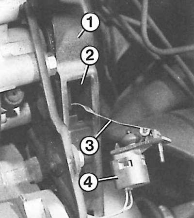
1 - cover; 2 - a window for checking the belt tension; 3 - sliding contact; 4 - switch
Toothed belt deflection
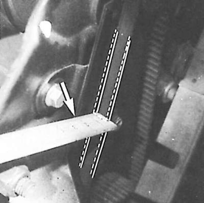
The deflection of the toothed belt at the point indicated by the arrow should be 5 mm under normal tension.
During the operation of the car, it is necessary to periodically check the tension of the toothed belt, the deflection of which from pressing a finger on the middle of the belt should be equal to 5 mm. The check is made through the window in the ABS timing belt cover.
With the ignition on, turn on the switch and press the sliding contact on the belt. If the warning light comes on, it indicates that the belt tension is insufficient.
To prevent blocking of the rear wheels on cars with an anti-lock braking system, a pressure regulator is installed in the drive of the brake mechanisms of the rear wheels, depending on the load on the rear axle of the car. With an increase in load, it provides the passage of fluid to the wheel cylinders of the rear brakes, which increases the pressure in their circuit and improves the efficiency of the rear brake mechanisms. With a decrease in load, the regulator reduces the fluid supply to the brake mechanisms until it is completely cut off, as a result of which the pressure in the rear brake drive decreases and the likelihood that the rear wheels will be blocked earlier than the front wheels is reduced. This prevents the rear wheels from slipping and the vehicle from skidding.
Visitor comments