Vehicles with 1.6L Zetec-SE/1.4L engine
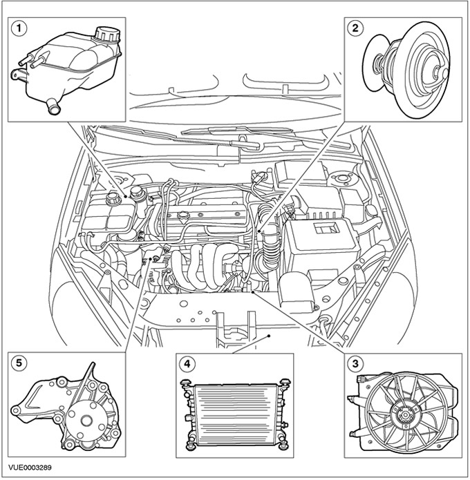
| Pos. | Spare Part No | Name |
| 1 | - | Expansion tank of the cooling system |
| 2 | - | Thermostat |
| 3 | - | Cooling fan motor and shroud |
| 4 | - | Radiator |
| 5 | - | Water pump |
Vehicles with 1.6L Duratec engine
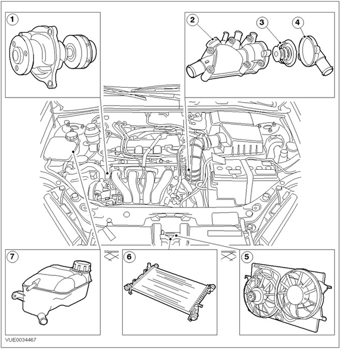
| Pos. | Spare Part No | Name |
| 1 | - | Water pump |
| 2 | - | thermostat housing |
| 3 | - | Thermostat |
| 4 | - | thermostat cover |
| 5 | - | Cooling Fan Shroud |
| 6 | - | Radiator |
| 7 | - | Expansion tank of the cooling system |
Vehicles with 1.8L/2.0L/1.6L Zetec-E engine
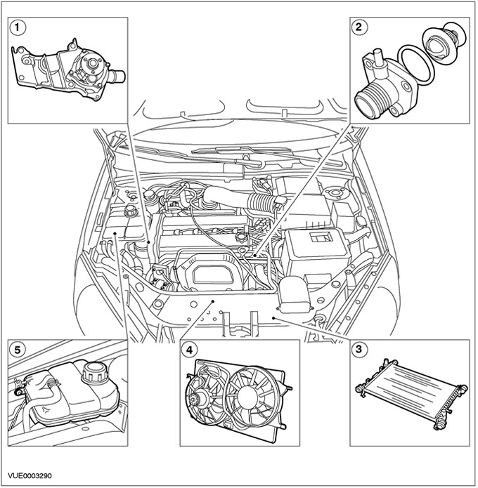
| Pos. | Spare Part No | Name |
| 1 | - | Water pump |
| 2 | - | Thermostat |
| 3 | - | Radiator |
| 4 | - | Cooling fan motor and shroud |
| 5 | - | Expansion tank of the cooling system |
Vehicles with 1.8L Diesel engine
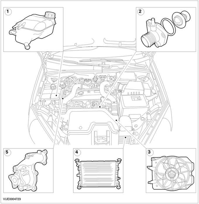
| Pos. | Spare Part No | Name |
| 1 | - | Expansion tank of the cooling system |
| 2 | - | Thermostat |
| 3 | - | Electric motor and casing |
| 4 | - | Radiator |
| 5 | - | Water pump |
Paraffin-filled thermostat provides fast engine warm-up. This is achieved by limiting coolant flow at low operating temperatures. The thermostat also helps maintain the engine's operating temperature within predetermined limits.
WARNING: When working in close proximity to the engine cooling fan, disconnect the wires from the battery. The fan is controlled by the engine management system and an increase in coolant temperature may cause the fan to turn on even when the ignition is off. Failure to follow this instruction may result in injury.
Fan (s) cooling is enclosed in a casing located behind the radiator.
Engine coolant
WARNING: Engine coolant contains monoethylene glycol and other additives that are poisonous if ingested and can be absorbed into the skin after prolonged contact.
The engine coolant concentration should be checked with a hydrometer (hydrometer) through the neck of the expansion tank. Acceptable operating density range (sg) properly balanced fluids - between 1.06 and 1.07 kg/l, which corresponds to an engine coolant concentration in the range between 40% and 55%. If the concentration falls below 40%, there is insufficient protection against low temperature exposure and corrosion resistance is insufficient. In such cases, the concentration should be brought to normal.
The coolant used can be either Motocraft Super Plus 4 blue-green or Motocraft Super Plus 2000 orange. Motocraft Super Plus 4 is a non-silicate organic acid coolant (OAT), and should not be mixed with other types of coolant. When adding coolant, use only coolant that meets the correct specification and is compatible with the existing coolant. For more information, please refer to the Specifications chapter available in this section.
Coolant replacement
WARNING: When relieving pressure in the cooling system, cover the expansion tank cap with a piece of thick cloth to prevent the danger of coolant scalding. Failure to follow this instruction may result in injury.
CAUTION: When draining the coolant or replacing any components of the cooling system, do not allow coolant to come into contact with the timing belt or accessory drive belt. Remove the belt if necessary. Dirty belt can damage it.
NOTE: As long as the coolant is not contaminated with other liquids or foreign matter, the good anti-corrosion properties of this coolant allow it to be reused after replacing the aluminum cooling system elements, but the concentration of the liquid should always be checked and kept within specifications.
This coolant should be changed after 10 years or 150,000 miles, whichever comes first. Only fill the cooling system with coolant that meets the correct specification and is compatible with the existing coolant. For more information, please refer to the Specifications chapter available in this section.
Reliable cooling
To the powertrain control module (PCM) The engine has a strategy that will control the engine if the engine starts to overheat.
If the engine starts to overheat, the 1st stage of the strategy is activated. Cylinder head temperature sensor (SNT) sends a signal to the PCM module, which instructs the temperature gauge to move into the red zone.
If the engine does not turn off and the temperature continues to rise, the control lamp lights up «Power Train Check» («Checking the power unit»). This indicates to the driver that the engine is approaching critical limits and should be stopped. At this point, the PCM generates DTC p1285, which can be retrieved using WDS.
If the driver ignores the warning light and the temperature gauge, the 2nd stage of the strategy is activated. The PCM takes control of the engine when two cylinders are turned off and the engine speed is limited to less than 3000 rpm. At the same time, the malfunction indicator lamp lights up (MIL). This indicates that significant permanent engine damage may occur and this will affect emissions levels. At this point, the PCM generates DTC p1299, which can be retrieved using WDS.
Air is sucked into the deactivated cylinders, which help regulate the temperature of the engine's internal components. Cylinder deactivation alternates between cylinders to ensure uniform cooling of all cylinders.
NOTE: If the driver uses a large throttle stroke (for example, when overtaking), when the PCM activates engine shutdown (2nd stage), the shutdown will be delayed by 10 seconds.
NOTE: Once 2-cylinder operation is activated, the engine will not return to 4-cylinder operation, even if the temperature should drop, until the ignition is turned off and then back on.
NOTE: MIL can only be cleared when using WDS after troubleshooting and clearing DTCs.
If the engine temperature continues to rise, the 3rd stage of the strategy comes into play. This results in a complete shutdown of the engine before serious damage or seizing occurs. The powertrain check lamp starts flashing to indicate to the driver that the engine will be shut off after 30 seconds. This gives the driver time to select a suitable parking space.
Visitor comments