Contents: Removal ↳ Installation ↳
Special tool
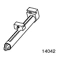 | Compressor for coil springs 204-167 (14-042) |
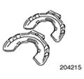 | Adapters for 204-167 204-215 (15-111) |
General equipment:
- Transmission jack
- Bridge stand
- Fixing clamp
Removal
1. Remove the wheels and tires. For additional information, refer to Section 204-04.
2.
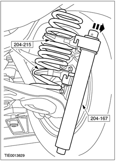
WARNING: Since the spring is under tension, use extreme caution. Failure to do so may result in injury.
Using special tools, remove the spring.
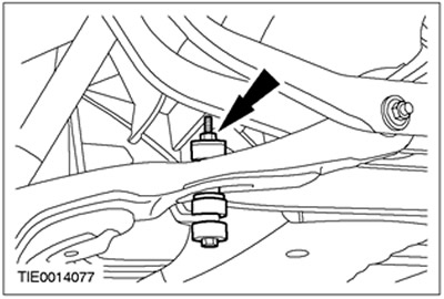
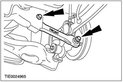
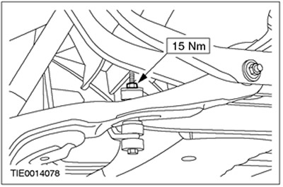
3. Disconnect the stabilizer bar from the rear lower arm on both sides.
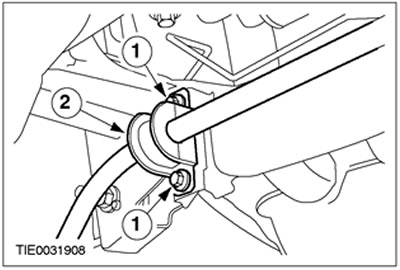
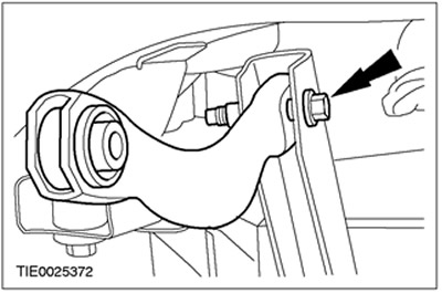
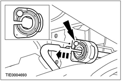
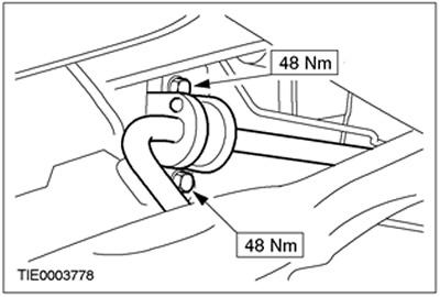
4. Remove the stabilizer bar clamps (left side shown).
- 1. Unscrew the mounting bolts.
- 2.Remove the clamp.
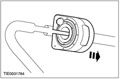
5. Remove the anti-roll bar.
6. Remove the anti-roll bar bushings.
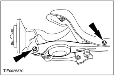
7. Remove the rear lower control arms (left side shown).
8.
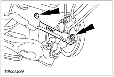
CAUTION: The front lower control arm is marked "FRONT". Mark the position of the front lower control arm to aid in installation.
Remove the front lower control arms (left side shown).
9. Disconnect the upper control arms from the wheel knuckles (left side shown).
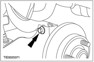
10.
NOTE: Mark the position of the upper arms to facilitate installation.
Remove the upper control arms (left side shown).

11.
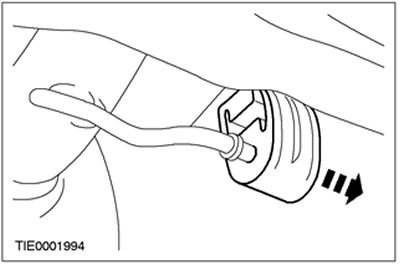
NOTE: Support the exhaust system components using a suitable axle stand.
Disconnect the exhaust system from the exhaust system hanger cross member.
- Lower the exhaust system to provide sufficient clearance relative to the cross member.

12.
WARNING: Make sure the crossmember is secured to the transmission jack. Failure to do so may result in personal injury.
Using a suitable clamp, secure the crossmember to the transmission jack.
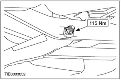
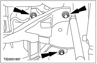
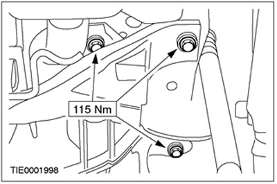
13. Remove the cross member.
- Remove the mounting bolts on both sides.
Installation
NOTE: Final tightening of rear suspension components should be performed at the calculated height.
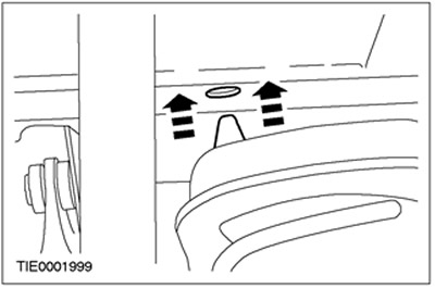
1.
CAUTION: Make sure the cross member ball bearing washers are installed correctly.
Using a suitable transmission jack, position the crossmember in the required position.
2. Install the cross member.
- Install the mounting bolts on both sides.
3. Remove the retaining clamp.
4. Lower and remove the transmission jack.
5. Fasten the exhaust system components to the cross member of the exhaust system suspension support.
- Remove the bridge support.
6.
NOTE: Do not fully tighten the upper control arm mounting bolts at this stage.
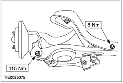
Attach the upper control arms to the crossmember (left side shown).
7.
NOTE: Do not fully tighten the upper control arm mounting bolts at this stage.
Install the upper control arms (left side shown).

8.
NOTE: Do not fully tighten the front lower control arm mounting bolts at this stage.
Install the front lower control arms (left side shown).
9.
NOTE: Do not fully tighten the rear lower control arm mounting bolts at this stage.
Install the rear lower control arms (left side shown).

10. Set the suspension to the design height. Refer to Section 204-00 for additional information.
11. Tighten the upper control arm to cross member bolts (left side shown).
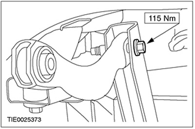
12. Tighten the upper control arm to wheel knuckle bolts (left side shown).
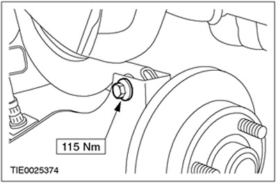
13. Tighten the front lower control arm mounting bolts on both sides.
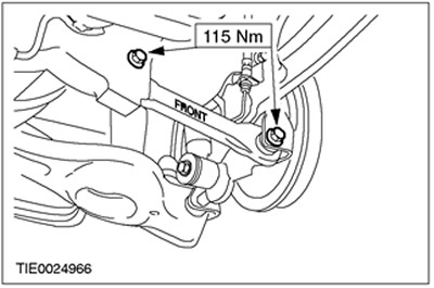
14. Tighten the rear lower control arm mounting bolts on both sides.
15.
NOTE: Do not secure the stabilizer bar to the rear lower control arms at this stage.
Install the anti-roll bar. For more information, refer to the Anti-roll Bar chapter in this section.
16.
CAUTION: The stabilizer bushings must be correctly positioned on the stabilizer. Do not use grease.
NOTE: Make sure the bushing nipple is located on the left side.
Install the bushing on the anti-roll bar on both sides.
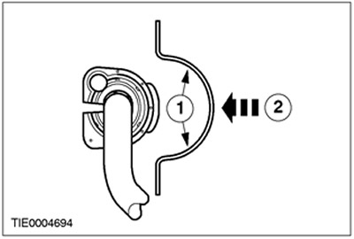
17. Install the stabilizer bar clamps on both sides.
- 1. Wet the clamps with water to facilitate installation.
- 2.Press the clamp onto the sleeve on both sides.
18. Install the anti-roll bar.
19. Lower the suspension, moving it out of the calculated height position.
20. Secure the anti-roll bar to the rear lower arm on both sides.
21. Install the springs. For more information, refer to the Spring chapter in this section.
22. Install the wheels and tires. For additional information, refer to Section 204-04.
23. Check and adjust wheel alignment if necessary. Refer to Section 204-00 for additional information.
24.
NOTE: Final tightening of the rear lower arm adjusting cam nuts should be performed with the vehicle resting on the drive wheels.
Tighten the rear lower arm adjusting cam nuts.