


Contents: Relay ↳ Fuses ↳ Location of fuses and relays in cars… ↳ Location of fuses and relays in cars… ↳
Relay
The location and purpose of the relays and fuses may differ depending on the vehicle modification. The designation of the controlled and protected electrical circuit is applied to the block cover.
The main unit is located in the rear of the engine compartment on the driver's side. The additional unit in cars manufactured before 01.1991 is located above the glove compartment, and in cars manufactured from 01.1991 onwards, in the rear of the engine compartment on the passenger side.
Relays can switch high currents over a distance, thus allowing the use of weak control switches and wiring.
Unlike mechanical switches, relays can be controlled by more than one signal.
Some relays can operate on a timer, for example, in the intermittent mode of windshield wipers or windshield heating.
If a fault is detected in a circuit equipped with a relay, it is always necessary to remember that the problem may lie in the relay itself. The test can be carried out by replacing it with a known good relay.
To replace a relay, remove it from its socket and insert a new one. Access to the relay in the main box is the same as to the fuses. Access to the relays located under the instrument panel is carried out after removing its upper part.
The sunroof drive relay is located in the overhead console.
Fuses
The battery is protected against short circuit by a fuse on the positive side.
The main fuse and relay box is located on the right side of the engine compartment, near the bulkhead. It contains up to 24 fuses and almost as many relays (depending on the equipment). The list of fuses is on the back of the box cover.
There is an additional fuse box in the car's interior, which can be accessed by opening the glove compartment lid.
The fuse for the radio is located on the radio power wire under the front panel on the left side near the heater.
All fuses are blade type and have a color corresponding to a certain fuse protection current. The serviceability of the fuse is determined by the presence of a wire conductor connecting the fuse contacts.
To replace a defective fuse, first turn off the corresponding electrical circuit. Remove the defective fuse from the socket using tweezers or special grips.
If a newly installed fuse immediately fails when voltage is applied, the protected electrical circuit should be checked. If the fuse protects several electrical circuits at the same time, they should be connected in turn in order to determine the faulty circuit by the fuse blowing and then eliminate the fault.
It is not recommended to replace a faulty fuse with a higher current, as this may cause serious damage, including fire.
Some electrical circuits, such as the electric window and seat positioner motors, have thermal relays installed instead of fuses that automatically turn on after the overload has been eliminated.
Location of fuses and relays in cars manufactured before 01.1991
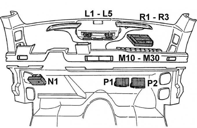
L1–L5 – on the bracket in the middle part of the instrument panel, M1–M10 – on the bracket behind the instrument panel on the glove compartment side, N1 – on the bracket under the instrument panel on the driver"s side, P1–P2 – under the instrument panel on the passenger side, R1–R3 – on the bracket under the instrument panel on the passenger side, S1 – on the left vertical panel of the engine compartment
L1 | Light signaling |
L2 | Rear fog light |
L3 | Time relay (in cars with automatic transmission) |
L4 | Fuel pump, air conditioner or cooling fan |
L5 | Anti-theft warning alarm |
M1 | Heating of the air sucked into the carburetor or fuel pump of the injection system |
M2 | Self-locking relay or fuel injectors of the injection system |
M3 | Heated windshield |
M4 | Windscreen heating time relay |
M5 | Cooling system fan |
M6 | Pump blockage |
M7 | Anti-lock braking system main relay |
M8 | Electronic modules of the anti-lock device |
M9 | Ground clearance adjustment |
M10 | Idle control or air conditioning |
N1 | Incandescent lamp failure indicator |
R1 | Braking system with ABS |
R2 | Fuel injection system control unit |
R1 | Automatic maintenance of vehicle speed |
R2 | Warning signal |
R3 | Seats |
S1 | Diesel Engine Glow Plug Control |
Fuses
№ | Current, A | Protected circuit |
1 | 20 | Left high beam and additional headlight |
2 | 20 | Right high beam and additional headlight |
3 | 10 | Left low beam |
4 | 10 | Right low beam and headlight range control |
5 | 10 | Left side light |
6 | 10 | Right side light |
7 | 15 | Interior and number plate lighting |
8 | 15 | Control of heated windshield, air conditioning and ride height adjustment |
9 | 30 | Headlight wiper, rear door lock |
10 | 20 | Central locking control, interior lighting, heated rear view mirror and clock |
11 | 30 | Fuel injection pump or air conditioner |
12 | 10 | Emergency light signaling |
13 | 30 | Heated seats, cigarette lighter |
14 | 30 | Sound signal |
15 | 30 | Windscreen wipers, windscreen washers |
16 | 30 | Rear window and seat heaters |
17 | 20 | Fog lights |
18 | 30 | Heating system fan |
19 | – | Spare |
20 | 15 | Direction indicators, rear fog lights |
21 | 15 | Brake lights |
22 | 10 | Instruments and control |
23 | 30 | Front window lift and electric sunroof |
24 | 30 | Rear door window lift and seat back adjustment |
Relay
№ I | Ignition chain |
№ II | Heated rear window and outside rearview mirror with automatic switch-off |
№ III | Power windows and sunroof |
№ IV | Backup or seat belt warning light |
№ V | Windscreen wiper mode programmer |
№ VI | Rear window wiper mode programmer |
№ VII | Headlight washers |
№ VIII | Temporary switch for car interior lighting |
№ IX | Seat adjustment |
№ X | Headlights |
№ XI | Auxiliary engine operating mode relay |
№ XII | Starter interlock relay |
A | Reserve |
IN | Radio |
WITH | Sound signal |
D | Rear door lock |
E | Reserve |
F | Low beam headlights |
G | Seat heaters |
H | Front fog lights |
Additional fuse box
Located above the glove compartment. To access the fuses, open the glove compartment and open the special cover at the top of the glove compartment.
| Color | Current, A | Protected circuit |
| Black | 20 | Fuel injection system fuel pump |
| Pink | 30 | Cooling system fan |
| Yellow | 20 | ABS system |
| Green | 30 | ABS system pump |
| Brown | 30 | Heated left side windshield |
| Brown | 30 | Heated right side windshield |
| Grey | 20 | Front seat adjustment |
| Orange | 20 | Ground clearance adjustment |
Location of fuses and relays in cars manufactured since 01.1991
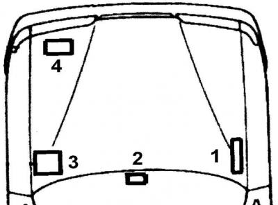
1 – additional fuse box, 2 – additional relay box under the instrument panel, 3 – main fuse box, 4 – additional relay box in the engine compartment
Main fuse and relay box
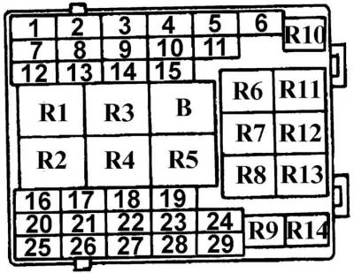
Fuses
№ | Current, A | Protected circuit |
1 | 15 | Fog lights |
2 | 5 | Left side light and number plate light |
3 | 10 | Light switch |
4 | 10 | Right side light and headlight range adjuster |
5 | 10 | Left low beam |
6 | 30 | Seat adjustment |
7 | 25 | Windscreen wipers and washers |
8 | 5 | Radio |
9 | 15 | Sound signal |
10 | 15 | High beam left |
11 | 15 | High beam right |
12 | 5 | Left side light |
13 | 20 | Ignition switch |
14 | 20 | Heating system fan |
15 | 10 | Rear fog light |
16 | 20 | Seat heaters |
17 | 20 | Cigarette lighter |
18 | – | Spare |
19 | 15 | Headlight washers |
20 | 20 | Rear window defroster |
21 | 10 | Electrically heated rear view mirror |
22 | 10 | Anti-theft alarm |
23 | 10 | Instrument cluster lighting |
24 | 15 | Central locking and interior lighting |
25 | 25 | Electric sunroof |
26 | 30 | Electric window lifter front doors |
27 | 10 | Stop signal |
28 | 30 | Electric rear window |
29 | 10 | Direction indicators and reversing lights |
Relay
R1 | Rear windshield wiper |
R2 | Windscreen wiper mode programmer |
R3 | Low beam |
R4 | Rear window defroster |
R5 | Temporary switch for car interior lighting |
R6 | High beam |
R7 | Reserve |
R8 | Headlight washer |
R9 | Fog lights |
R10 | Sound signal |
R11 | Starter interlock relay for cars with automatic transmission |
R12 | Self-locking relay |
R13 | Electric window lift |
R14 | Reserve |
Additional fuse and relay box
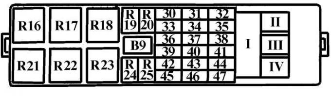
Fuses
№ | Current, A | Protected circuit |
30 | 20 | Ground clearance adjustment |
31 | 3 | EEC IV control unit |
32 | 30 | Anti-lock braking device (pump 2) |
33 | 20 | Power steering |
34 | 15 | Engine operating mode control relay |
35 | 30 | Radiator fan |
36 | 3 | Anti-lock braking system control unit |
37 | 20 | Control of engine operating modes |
38 | 30 | Right side windshield heater |
39 | – | Spare |
40 | 10 | Lambda probe |
41 | 30 | Left side windshield heater |
42 | 15 | High pressure fuel pump |
43 | – | Spare |
44 | 30 | Radiator fan |
45 | 10 | Emergency light signaling |
46 | 30 | Anti-lock braking system control unit |
47 | 30 | Anti-lock braking device (pump 1) |
I | 80 | Voltage to main fuse box |
II | 60 | Voltage to main fuse box |
III | 60 | Voltage to main fuse box |
IV | 50 | Diesel Engine Glow Plugs |
Relay
R16 | Anti-lock device |
R17 | High pressure fuel pump |
R18 | Windscreen heater |
R19 | Control of engine operating modes |
R20 | Ground clearance adjustment |
R21 | Ignition switch |
R22 | Radiator Fan (DOCH) |
R23 | Radiator fan or air conditioner |
R24 | Air conditioner |
R25 | Air conditioner |
Location of additional relays
The glow plug preheating relay for a diesel engine is located in the front right part of the engine compartment.
The relays for the anti-theft alarm, anti-lock brake system and automatic transmission downshift are located under the center of the instrument panel.
The window lift relay is located in the driver's door.
The rear wiper mode relay (Turnier) is located near the steering column.