- a fuel supply system that includes a fuel tank, an electric fuel pump module, pipelines, hoses, a fuel rail with injectors and a fuel pressure pulsation compensator;
- air supply system, consisting of an air filter, an air supply sleeve and a throttle assembly;
- a fuel vapor recovery system that includes an adsorber, an adsorber purge valve and connecting pipelines.
The functional purpose of the fuel supply system is to ensure the supply of the required amount of fuel to the engine in all operating modes. The engine is equipped with an electronic control system with distributed fuel injection. In the distributed fuel injection system, the functions of mixture formation and dosing of the air-fuel mixture supply to the engine cylinders are separated: the injectors carry out metered fuel injection into the intake pipe, and the amount of air required at each moment of engine operation is supplied by the throttle assembly. This control method makes it possible to ensure the optimal composition of the combustible mixture at each particular moment of engine operation, which allows obtaining maximum power with the lowest possible fuel consumption and low exhaust gas toxicity. The fuel injection system and the ignition system are controlled by an electronic engine control unit, which continuously monitors the engine load, the vehicle speed, the thermal state of the engine, and the optimal combustion process in the cylinders using appropriate sensors.
A feature of the Ford Focus II injection system is the synchronous operation of the injectors in accordance with the valve timing (the engine control unit receives information from the phase sensors). The controller turns on the injectors in series, and not in pairs, as in asynchronous injection systems. Each nozzle is activated through 720°of crankshaft rotation. However, in starting and dynamic modes of engine operation, an asynchronous method of fuel supply is used without synchronization with the rotation of the crankshaft.
The main sensor for the fuel injection system is the oxygen concentration sensor in the exhaust gases (Lambda probe). In the exhaust manifold of the R4 16V Duratec Ti-VCT engine, combined with exhaust gas converters (collector), two oxygen concentration sensors are installed (separately for the exhaust tracts of the 1st and 4th, 2nd and 3rd cylinders), which, together with the engine control unit and injectors, form a control loop for the composition of the air-fuel mixture supplied to the engine. Based on the signals from the sensors, the engine control unit determines the amount of unburned oxygen in the exhaust gases and, accordingly, evaluates the optimal composition of the air-fuel mixture entering the engine cylinders at any given time. Having fixed the deviation of the composition from the optimal 1:14 (respectively fuel and air), which ensures the most efficient operation of catalytic converters of exhaust gases, the control unit changes the composition of the mixture using injectors. Since the oxygen sensors are included in the feedback circuit of the engine control unit, the air-fuel ratio control loop is closed. A feature of the Ford Focus II engine management system is the presence, in addition to two control sensors, of two more diagnostic oxygen concentration sensors installed at the outlet of the converters. According to the composition of the gases that have passed through the converters, they determine the efficiency of the engine control system. If the engine control unit, based on information received from diagnostic oxygen concentration sensors, detects an excess of exhaust gas toxicity that cannot be eliminated by calibrating the control system, it turns on the engine malfunction warning light in the instrument cluster and stores the error code in memory for subsequent diagnostics.
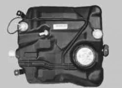
Fuel tank, molded from a special impact-resistant plastic, is installed under the floor of the body in its rear part and is attached with clamps. In order to prevent fuel vapor from entering the atmosphere, the tank is connected by a pipeline to the adsorber of the fuel vapor recovery system. An electric fuel pump is installed in the flanged hole in the upper part of the tank; branch pipes are made on the right side for connecting a filling pipe and a ventilation hose. From the pump, which includes coarse and fine fuel filters, fuel is supplied to the fuel rail mounted on the engine intake pipe. From the fuel rail, fuel is injected by injectors into the intake pipe.
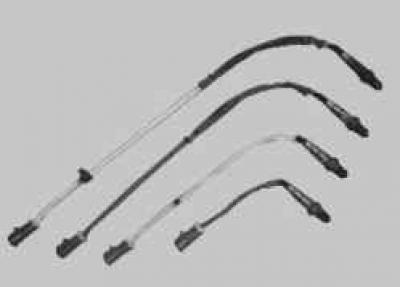
Fuel lines combined power systems, in the form of interconnected steel pipelines and rubber hoses.
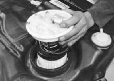
Fuel pump submersible, with electric drive, rotary type, with coarse and fine fuel filters, with fuel pressure regulator. The pump is installed in the fuel tank, which reduces the possibility of vapor lock, since the fuel is supplied under pressure, and not under vacuum. The fuel pump supplies fuel from the fuel tank through the fuel line to the fuel rail at a pressure of about 380 kPa (approximately 360 kPa at idle).
Fuel filter fine cleaning - full-flow, installed in the fuel pump module housing. If the filter is clogged, it is necessary to replace the housing assembly with the filter, since the assembly is made non-separable.
fuel rail 5 (pic. 5.26), which is a hollow tubular part with holes for installing injectors 8 and a compensator 2 for fuel pressure pulsations, serves to supply fuel to the injectors and is fixed on the intake pipe. The injectors and the pressure pulsation compensator are sealed in their sockets with rubber rings 3, 4 and 7. The complete injector ramp is inserted into the inlet pipe openings with the injector shanks and secured with two nuts.
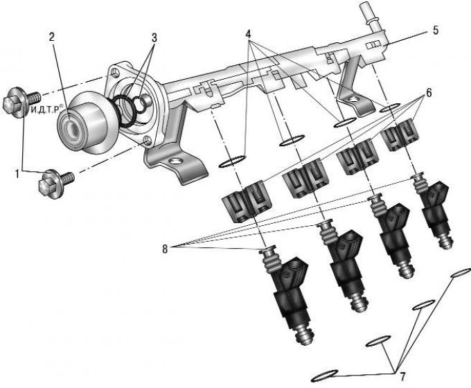
Pic. 5.26. Fuel rail with injectors and fuel pressure pulsation compensator: 1 – bolts for fastening the fuel pressure pulsation compensator; 2 – fuel pressure pulsation compensator; 3 - sealing rings of the fuel pressure pulsation compensator; 4 – top sealing rings of injectors; 5 - fuel rail; 6 - nozzle holders; 7 - lower sealing rings of injectors; 8 - nozzles
NOTE: Depending on the fuel pulsation compensator version, the small o-ring may be missing.
nozzles 8 (see fig. 5.26) with their atomizers enter the openings of the inlet pipe. In the inlet pipe openings, the nozzles are sealed with rubber sealing rings 7. The nozzle is designed for metered injection of fuel into the engine cylinder and is a high-precision electromechanical valve in which the shut-off valve needle is pressed against the seat by a spring. When an electrical impulse is applied from the control unit to the electromagnet winding, the needle rises and opens the atomizer hole - fuel is supplied to the engine intake pipe. The amount of fuel injected by the injector depends on the duration of the electrical impulse.
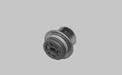
Fuel pressure pulsation compensator installed at the end of the fuel rail and serves to maintain a constant fuel pressure in the rail when it drops sharply in the fuel line, caused, for example, by a significant increase in fuel consumption during intensive acceleration of the car.
Air filter installed on the left side of the engine compartment on a special bracket. The filter element is paper, flat, with a large area of the filtering surface. The filter is connected by a rubber corrugated air supply sleeve to the throttle assembly.
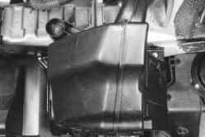
The branch pipe in the lower part of the filter housing is installed with an interference fit in the neck of the intake silencer, located under the left front fender of the car.
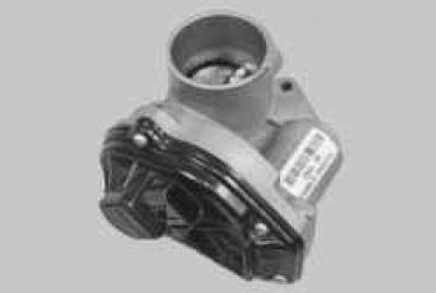
Throttle assembly, which is the simplest control device, serves to change the amount of main air supplied to the engine intake system, is installed on the inlet flange of the intake pipe and is attached with screws. A molded rubber sleeve is put on the inlet pipe of the throttle assembly, fixed with a clamp and connecting the throttle assembly with the air filter.
The throttle assembly includes a throttle position sensor and a throttle control stepper motor. There is no mechanical connection between the throttle assembly and the throttle control pedal. So-called «electronic» the throttle control pedal transmits information about the degree of depression on the pedal to the electronic engine control unit, which, in turn, taking into account the vehicle speed, the gear engaged, the engine load and the crankshaft speed, opens the throttle valve to the desired angle.
Evaporative Emission System prevents the release of fuel vapors from the power supply system into the atmosphere, which adversely affect the environment.
The system uses the method of vapor absorption by a carbon adsorber. It is installed at the rear of the body base and is connected by pipelines to the fuel tank and the purge valve.
In the engine compartment, on the inlet pipe, there is an adsorber purge solenoid valve, which switches the operating modes of the system based on signals from the engine control unit.
Fuel vapors from the fuel tank are constantly discharged through the pipeline and accumulate in the adsorber filled with activated carbon (adsorbent). When the engine is running, it regenerates (recovery) adsorbent by purging the adsorber with fresh air entering the system under the action of vacuum transmitted through the pipeline from the inlet pipe to the adsorber cavity when the purge valve is opened. The control unit regulates the degree of purge of the adsorber, depending on the mode of operation of the engine, by supplying a signal to the valve with a variable pulse frequency.
Fuel vapor from the adsorber through the pipeline enters the engine intake pipe and burns in the cylinders.
Malfunctions of the fuel vapor recovery system entail idle instability, engine shutdown, increased toxicity of exhaust gases and deterioration in driving performance of the vehicle.
Visitor comments