|
STATES |
DETAILS/RESULTS/ACTIONS |
|
A1: BATTERY TEST |
|
|
1 Test battery using FDS 2000. See Section 414-00 for more information. |
|
|
• Is the battery OK? |
|
|
→ Yes |
|
|
Go to A2 Go to PINPOINT TEST A |
|
|
→ No |
|
|
Install a new battery. Check the correct operation of the system. |
|
|
A2: STARTER RELAY CHECK |
|
|
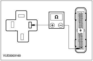
1 Disconnect the starter relay. |
|
|
2 Perform element check for ISO minirelay. For more information, refer to the wiring diagram. |
|
|
• Is the relay OK? |
|
|
→ Yes |
|
|
Go to A3 Go to PINPOINT TEST A |
|
|
→ No |
|
|
Install a new starter relay. Check the correct operation of the system. |
|
|
A3: CHECKING THE VOLTAGE SUPPLY TO THE 50-BB17 STARTER RELAY CIRCUIT (GRAY ORANGE) |
|
|
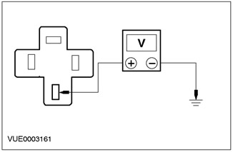
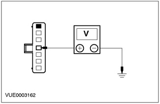
1 Using a digital multimeter, measure the voltage between pin 3 of the starter relay on the wiring harness side and "weight". |
|
• Is the voltage over 10V? |
|
|
→ Yes |
|
|
Go to A4 Go to PINPOINT TEST A |
|
|
→ No |
|
|
Repair electrical circuit 50-BB17 (gray-orange). Check the correct operation of the system. |
|
|
A4: 50-BB12 ELECTRICAL CIRCUIT CHECK (GRAY) FOR A BREAK |
|
|
1 Enter the OFF position. |
|
|
2 Disconnect Line connector C80. |
|
|
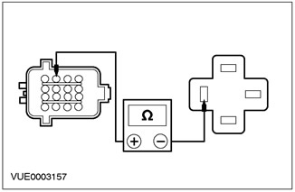
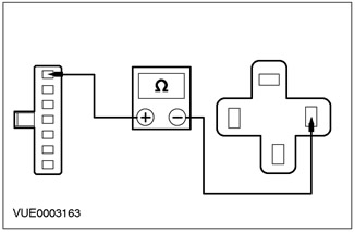
3 Using a digital multimeter, measure the resistance between pin 12 of connector C80, circuit 50-BB12 (gray), and pin 5 of the starter relay. |
|
• Is the resistance less than 5 ohms? |
|
|
→ Yes |
|
|
Go to A5 Go to PINPOINT TEST A |
|
|
→ No |
|
|
Repair circuit 50-BB12 (gray). Check the correct operation of the system. |
|
|
A5: CHECKING THE POWER SUPPLY TO THE STARTER |
|
|
1 Connect the Starter Relay. |
|

|
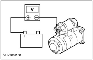
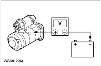
2 Using a digital multimeter, measure the voltage between starter pin 30 on the starter side and battery positive with the ignition switch in position III. |
|
• Is the voltage less than 0.5 V? |
|
|
→ Yes |
|
|
If the vehicle is equipped with an automatic transaxle, Go to A6 Go to PINPOINT TEST A |
|
|
Repair circuit 50-BB12 (gray). Check the correct operation of the system. |
|
|
→ No |
|
|
Clean and tighten all battery positive circuit connections. Check the correct operation of the system. If there is a problem, install a new positive battery cable. |
|
|
A6: CHECKING THE OPERATION OF THE 50S-BB12 ELECTRICAL CIRCUIT (GRAY) I 50-BB14 (GRAY-RED) GEAR SHIFT MODE SWITCHES (AUTOMATIC GEARBOX WITH DRIVE AXLE) |
|
|
1 Using a digital multimeter, measure the resistance between pin 6, circuit 50S-BB12 (gray), and pin 9, electrical circuit 50-BB14 (grey-red), connector C438 of the shift mode switch, on the side of the switch. |
|
• Is the resistance less than 5 ohms? |
|
|
→ Yes |
|
|
Repair electrical circuits 50S-BB12 (gray) or 50-BB14 (gray-red). Check the correct operation of the system. |
|
|
→ No |
|
|
Adjust the shift mode switch. If there is a problem, install a new shift mode sensor. |
|
PINPOINT TEST B: ENGINE DOES NOT TURN AND RELAY DOES NOT CLICK
|
STATES |
DETAILS/RESULTS/ACTIONS |
|
B1: CHECKING PATS STATUS |
|
|
1 Watch the PATS indicator light. |
|
|
• Does the warning light flash when you try to start the engine? |
|
|
→ Yes |
|
|
Malfunction in the PATS system. See Section 419-01A / 419-01B for more information. |
|
|
→ No |
|
|
Go to B2 Go to PINPOINT TEST B |
|
|
B2: CHECKING OPERATION OF THE STARTER RELAY |
|
|
1 Disconnect the starter relay. |
|
|
2 Perform element check for ISO minirelay. For more information, refer to the wiring diagram. |
|
|
• Is the relay OK? |
|
|
→ Yes |
|
|
Go to B3 Go to PINPOINT TEST B |
|
|
→ No |
|
|
Install a new starter relay. Check the correct operation of the system. |
|
|
B3: BATTERY STATUS CHECK |
|
|
1 Test battery using FDS 2000. See Section 414-00 for more information. |
|
|
• Is the battery OK? |
|
|
→ Yes |
|
|
Go to B4 Go to PINPOINT TEST B |
|
|
→ No |
|
|
Install a new battery. Check the correct operation of the system. |
|
|
B4: FUSE CHECK 10 (10A) and 8 (30A). |
|
|
1 CHECK Fuse 10 (10A). |
|
|
2 CHECK Fuse 8 (30A). |
|
|
3 Check fuses 10 (10A) and 8 (30A). |
|
|
• Are the fuses OK? |
|
|
→ Yes |
|
|
Go to B5 Go to PINPOINT TEST B |
|
|
→ No |
|
|
Install a new fuse if necessary (And). If the fuse (And) fails again, check the electrical circuit for a short circuit. |
|
|
B5: CHECKING THE SWITCHED POWER SUPPLY TO THE STARTER RELAY |
|
|
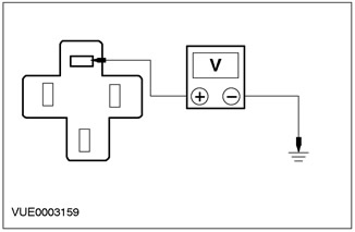
1 Using a digital multimeter, measure the voltage between pin 1 of the starter relay, harness side, and "weight" when the ignition switch is in position III. |
|
• Is the voltage over 10V? |
|
|
→ Yes |
|
|
Go to B6 Go to PINPOINT TEST B |
|
|
→ No |
|
|
Go to B7 Go to PINPOINT TEST B |
|
|
B6: PATS ELECTRICAL CIRCUIT CHECK FOR ELECTRICAL CIRCUIT 31S-BB16 STARTER RELAY |
|
|
1 Enter the OFF position. |
|
|
2 Disconnect the C415 PCM. |
|
|
3 Using a digital multimeter, measure the resistance between pin 2 of the starter relay, circuit 31S-BB16 (black and red), and pin 27 of the C415 PCM connector, on the wiring harness side |
|
• Is the resistance less than 5 ohms? |
|
|
→ Yes |
|
|
Malfunction in the PATS system. See Section 419-01A / 419-01B for more information. |
|
|
→ No |
|
|
Repair circuit 31S-BB16 (black and red). Check the correct operation of the system. |
|
|
B7: VOLTAGE CHECK IN THE ELECTRICAL CIRCUIT 30-BB9 (RED) IGNITION SWITCH |
|
|
1 Disconnect the C456 ignition switch. |
|
|
2 Using a digital multimeter, measure the voltage between pin 4 of connector C456 of the ignition switch, circuit 30-BB9 (red), on the wiring harness side and "weight" |
|
• Is the voltage over 10V? |
|
|
→ Yes |
|
|
Go to B8 Go to PINPOINT TEST B |
|
|
→ No |
|
|
Repair circuit 30-BB9 (red). Check the correct operation of the system. If there is a problem, repair or install a new battery junction box. |
|
|
B8: 15-DA1 ELECTRICAL CIRCUIT CHECK (GREEN YELLOW) FOR A BREAK IN THE CHAIN |
|
|
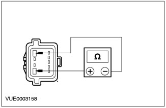
1 Using a digital multimeter, measure the resistance between pin 1 of connector C456 of the ignition switch, circuit 15-DA1 (green-yellow), and pin 1 of the starter relay. |
|
• Is the resistance less than 5 ohms? |
|
|
→ Yes |
|
|
Install a new ignition switch. Check the correct operation of the system. |
|
|
→ No |
|
|
Repair circuit 15-DA1 (green-yellow). Check the correct operation of the system. |
|
PINPOINT TEST C: ENGINE TURNS SLOWLY.
|
STATES |
DETAILS/RESULTS/ACTIONS |
|
C1: STARTER LOAD CHECK |
|
|
1 Perform starter load test. For more information, refer to Checking the Starter Load found in this section.. |
|
|
• Is the starter OK? |
|
|
→ Yes |
|
|
Go to C2 Go to PINPOINT TEST C |
|
|
→ No |
|
|
Install a new starter. Check the correct operation of the system. |
|
|
C2: VOLTAGE DROP CHECK |
|
|
1 Using a digital multimeter, measure the voltage between starter pin 30 on the starter side and battery positive with the ignition switch in position III. |
|
• Is the voltage less than 0.5 V? |
|
|
→ Yes |
|
|
Go to C3 Go to PINPOINT TEST C |
|
|
→ No |
|
|
Clean and tighten all battery positive circuit connections. Check the correct operation of the system. If there is a problem, install a new positive battery cable. |
|
|
C3: ELECTRICAL CIRCUIT CHECK ON "MASS" |
|
|
1 Using a digital multimeter, measure the voltage between the starter housing and the negative battery terminal with the ignition switch in position III. |
|
• Is the voltage less than 0.5 V? |
|
|
→ Yes |
|
|
Run battery and charging system diagnostics. See Section 414-00 for more information. |
|
|
→ No |
|
|
Clean and tighten all negative battery circuit connections, starter mountings, and ground wire between body and engine. Check the correct operation of the system. If there is a problem, install a new battery ground wire. |
|
Item checks
Starter under load
The battery must be fully charged before beginning the starter load test. To inspect and test the battery: Refer to Section 414-00 for more information.
- 1. Apply the parking brake and shift the transmission to neutral.
- 2. Connect the FDS2000 and follow the on-screen instructions.
Starter without load
- 1. Remove the starter. For more information refer to the Starter available in this section.
- 2. Connect the FDS2000 and follow the on-screen instructions.
- 3. If the voltage is below the prescribed value or the current is above the prescribed value, refer to the Symptom Table to determine the cause and corrective action "Starter without load. Test Results".
Visitor comments