|
STATES |
DETAILS/RESULTS/ACTIONS |
|
K1: CHECK FUSE F56 (CJB) |
|
|
1 Enter the OFF position. |
|
|
2 CHECK Fuse F56 (CJB). |
|
|
3 CHECK FUSE F56 (20 A) |
|
|
• Is the fuse good? |
|
|
→ Yes |
|
|
Go to K2 |
|
|
→ No |
|
|
INSTALL a new fuse F56 (20 A) and CHECK system operation. If the fuse blows again, LOCATE and REPAIR the short circuit using the wiring diagrams. CHECK the system is working properly. |
|
|
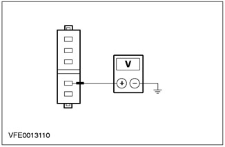
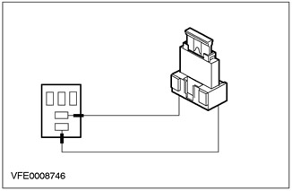
K2: CHECK FUSE VOLTAGE F56 (CJB) |
|
|
1 Enter the OFF position. |
|
|
2 Connect Fuse F56 (CJB). |
|
|
3 Drive the ON position. |
|
|
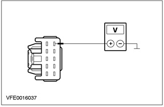
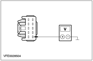
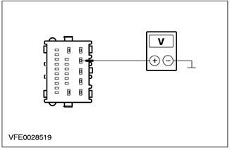
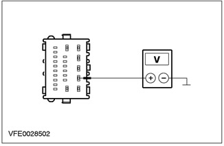
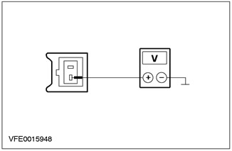
4 Measure the voltage between fuse F56 and "weight ". |
|
|
• Does the battery voltage register? |
|
|
→ Yes |
|
|
Rear window wiper not working: Go to K3 |
|
|
The windshield wipe function with respect to the rear wipe mode and the normal windshield wipe function do not work: Go to K5 |
|
|
→ No |
|
|
CHECK CJB; if necessary, INSTALL a new CJB. CHECK the system is working properly. |
|
|
K3: CHECK FUSE F43 (CJB) |
|
|
1 Enter the OFF position. |
|
|
2 CHECK Fuse F43 (CJB). |
|
|
3 CHECK FUSE F43 (15 A) |
|
|
• Is the fuse good? |
|
|
→ Yes |
|
|
Go to K4 |
|
|
→ No |
|
|
INSTALL a new fuse F43 (15 A) and CHECK system operation. If the fuse blows again, LOCATE and REPAIR the short circuit using the wiring diagrams. CHECK the system is working properly. |
|
|
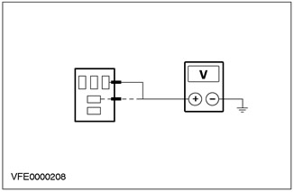
K4: CHECK FUSE VOLTAGE F43 (CJB) |
|
|
1 Enter the OFF position. |
|
|
2 Connect Fuse F43 (CJB). |
|
|
3 Drive the ON position. |
|
|
4 Measure the voltage between fuse F43 and "weight". |
|
|
• Does the battery voltage register? |
|
|
→ Yes |
|
|
Go to K5 |
|
|
→ No |
|
|
CHECK CJB; if necessary, INSTALL a new CJB. CHECK the system is working properly. |
|
|
K5: CHECK THE SYSTEM USING WDS |
|
|
1 Connect the diagnostic tool. |
|
|
2 Check the system using WDS |
|
|
• Any DTCs registered (DTC)? |
|
|
→ Yes |
|
|
PROCESS DTCs according to WDS instructions. CLEAR fault memory and CHECK the system is operating correctly. |
|
|
→ No |
|
|
Go to K6 |
|
|
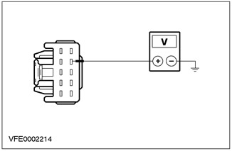
K6: CHECK VOLTAGE AT WIPER/WASH SWITCH |
|
|
1 Enter the OFF position. |
|
|
2 Disconnect Wiper/Washer Switch - C441. |
|
|
3 Drive the ON position. |
|
|
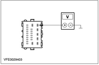
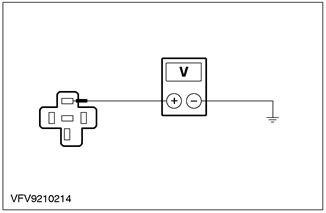
4 Measure the voltage between pin 6 of C441 wiper/washer switch circuit 15-KA19 (A) (green/orange), on the wiring harness side, and "weight". |
|
• Does the battery voltage register? |
|
|
→ Yes |
|
|
Go to K7 |
|
|
→ No |
|
|
LOCATE and REPAIR open circuit between fuse F56 and wiper/washer switch using the electrical circuit diagrams. If necessary, INSTALL a new CJB. CHECK the system is working properly. |
|
|
K7: INSPECT WIPER/WASH SWITCH |
|
|
1 Enter the OFF position. |
|
|
2 Test the wiper/washer switch according to the component test instructions included with the electrical diagrams. |
|
|
• Is the wiper/washer switch OK? |
|
|
→ Yes |
|
|
Windshield wipers not working: Go to K14 |
|
|
Rear window wiper not working: Go to K8 |
|
|
→ No |
|
|
INSTALL a new wiper/washer switch. CHECK the system is working properly. |
|
|
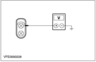
K8: CHECK REAR WIPER RELAY VOLTAGE (PIN 1) |
|
|
1 Enter the OFF position. |
|
|
2 Disconnect the Rear Wiper Relay - C1018. |
|
|
3 Drive the ON position. |
|
|
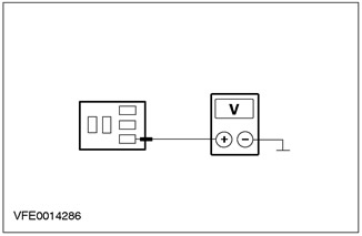
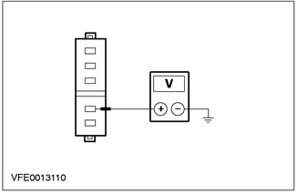
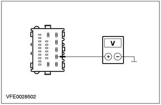
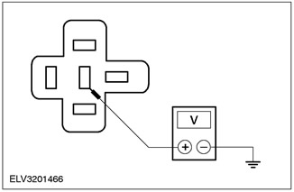
4 Measure the voltage between C1018 rear window wiper relay pin 1, CJB side, and "weight". |
|
• Does the battery voltage register? |
|
|
→ Yes |
|
|
Go to K9 |
|
|
→ No |
|
|
CHECK CJB; if necessary, INSTALL a new CJB. CHECK the system is working properly. |
|
|
K9: CHECK REAR WIPER RELAY VOLTAGE (PIN 5) |
|
|
1 Measure the voltage between C101 rear wiper relay pin 5, CJB side, and "weight". |
|
• Does the battery voltage register? |
|
|
→ Yes |
|
|
Go to K10 |
|
|
→ No |
|
|
CHECK CJB; if necessary, INSTALL a new CJB. CHECK the system is working properly. |
|
|
K10: INSPECT REAR WIPER RELAY POWER CIRCUIT |
|
|
1 Enter the OFF position. |
|
|
2 Disconnect the Rear Wiper Motor - C971. |
|
|
3 Connect the connection wire with fuse (15 A) to the C1018 rear window wiper relay connector, between pin 3 and pin 5, on the CJB side. |
|
4 Drive the ON position. |
|

|
5 Measure the voltage between pin 2 of the C971 rear window wiper motor circuit 32-KA28 (white/red), from the wiring side, and "weight". |
|
• Does the battery voltage register? |
|
|
→ Yes |
|
|
Go to K11 |
|
|
→ No |
|
|
LOCATE and REPAIR the open circuit between the rear window wiper relay and the rear window wiper motor using the electrical circuit diagrams. If necessary, INSTALL a new CJB. CHECK the system is working properly. |
|
|
K11: INSPECT REAR WIPER RELAY CONTROL CIRCUIT |
|
|
1 Enter the OFF position. |
|
|
2 Connect Rear Wiper Relay - C1018. |
|
|
3 Drive the ON position. |
|
|
4 Turn on REAR WIPER. |
|

|
5 Measure the voltage between pin 2 of the C971 rear window wiper motor circuit 32-KA28 (white/red), from the wiring side, and "weight". |
|
• Does the battery voltage register? |
|
|
→ Yes |
|
|
Go to K13 |
|
|
→ No |
|
|
INSPECT the rear window wiper relay in accordance with the component test instructions included with the wiring diagrams; if necessary, INSTALL the new item. If the relay is OK, Go to K12 |
|
|
K12: CHECK REAR WIPER MOTOR VOLTAGE |
|
|
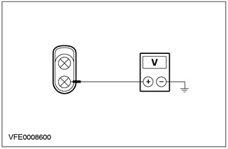
1 Measure the voltage between pin 1 of the C971 rear window wiper motor circuit 15-KA28 (green/brown), from the wiring side, and "weight". |
|
• Does the battery voltage register? |
|
|
→ Yes |
|
|
INSPECT wiper motor; if necessary, INSTALL the new element. CHECK the system is working properly. |
|
|
→ No |
|
|
LOCATE and REPAIR open circuit between fuse F43 (CJB) and the rear window wiper motor using the wiring diagrams. If necessary, INSTALL a new CJB. CHECK the system is working properly. |
|
|
K13: INSPECT REAR WIPER RELAY CONTROL CIRCUIT |
|
|
1 Enter the OFF position. |
|
|
2 Disconnect the Common Electronic Module (GEM) - C105. |
|
|
3 Drive the ON position. |
|
|
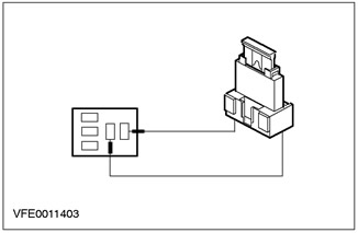
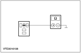
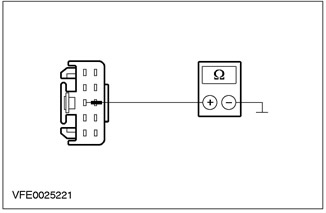
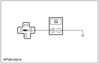
4 Measure the resistance between C1018 rear wiper relay pin 2, CJB side, and C105 general electronics pin 17 (GEM), electrical circuit 91S-KA29 (black/yellow), from the wiring harness side. |
|
• Is the resistance less than 2 ohms? |
|
|
→ Yes |
|
|
INSTALL a new common electronics module (GEM). CHECK the system is working properly. |
|
|
→ No |
|
|
LOCATE and REPAIR open circuit between rear window wiper relay and common electronic module (GEM), using electrical diagrams. If necessary, INSTALL a new CJB. CHECK the system is working properly. |
|
|
K14: CHECK WINDSHIELD WIPER MOTOR VOLTAGE |
|
|
1 Connect Wiper/Washer Switch - C441. |
|
|
2 Disconnect the Windshield Wiper Motor - C848. |
|
|
3 Drive the ON position. |
|
|
4 Turn on the SLOW WIPER MODE. |
|

|
5 Measure the voltage between pin 5 of the C848 windshield wiper motor circuit 32-KA10 (white/green), from the wiring side, and "weight". |
|
• Does the battery voltage register? |
|
|
→ Yes |
|
|
Go to K15 |
|
|
→ No |
|
|
LOCATE and REPAIR open circuit 32-KA10 (white/green), between the wiper/washer switch and the wiper motor using the wiring diagrams. CHECK the system is working properly. |
|
|
K15: CHECK WINDSHIELD WIPER MOTOR GROUND CONNECTION |
|
|
1 Enter the OFF position. |
|
|
2 Measure the resistance between C848 windshield wiper motor pin 1, circuit 31-KA9 (black), from the wiring side, and "weight". |
|
• Is the resistance less than 2 ohms? |
|
|
→ Yes |
|
|
INSPECT the windshield wiper motor according to the item test instructions included with this section; if necessary, INSTALL the new element. CHECK the system is working properly. |
|
|
→ No |
|
|
LOCATE and REPAIR open circuit 31-KA9 (black), between wiper motor and connection S121 ("weight" G37), using electrical diagrams. CHECK the system is working properly. |
|
PINPOINT TEST L: WIPER ON CONTINUOUSLY
|
STATES |
DETAILS/RESULTS/ACTIONS |
|
L1: CHECK THE SYSTEM USING WDS |
|
|
1 Connect the diagnostic tool. |
|
|
2 Check the system using WDS. |
|
|
• Any DTCs registered (DTC)? |
|
|
→ Yes |
|
|
PROCESS DTCs according to WDS instructions. CLEAR fault memory and CHECK the system is operating correctly. |
|
|
→ No |
|
|
Windshield wipers on continuously: Go to L2 |
|
|
Rear wiper on continuously: Go to L12 |
|
|
L2: IDENTIFY THE STATE IN WHICH THE FAULT IS APPEARING. |
|
|
1 Determine the state in which the fault occurs. |
|
|
• Are the purifiers on continuously in the low speed purge mode? |
|
|
→ Yes |
|
|
Go to L3 |
|
|
→ No |
|
|
To intermittent cleaning mode: Go to L8 |
|
|
In high-speed cleaning mode: Go to L10 |
|
|
L3: IDENTIFY THE STATE IN WHICH THE FAULT IS MANIFESTED |
|
|
NOTE: Turn off the windshield wipers |
|
|
1 Enter the OFF position. |
|
|
2 Disconnect the Windshield Wiper Motor - C848. |
|
|
3 Drive the ON position. |
|
|
4 Measure the voltage between C848 pin 5 of the windshield wiper motor circuit 32-KA10 (white/green), from the wiring side, and "weight". |
|
• Does the battery voltage register? |
|
|
→ Yes |
|
|
Go to L4 |
|
|
→ No |
|
|
INSPECT the windshield wiper motor according to the item test instructions included with this section; if necessary, INSTALL the new item. CHECK the system is working properly. |
|
|
L4: INSPECT CIRCUIT 32-KA10 (WHITE/GREEN) ON THE SECTION OF THE ELECTRIC MOTOR OF THE WINDSHIELD CLEANER FOR A SHORT CIRCUIT TO THE POWER SUPPLY |
|
|
1 Enter the OFF position. |
|
|
2 Disconnect Wiper/Washer Switch - C441. |
|
|
3 Drive the ON position. |
|

|
4 Measure the voltage between C848 pin 5 of the windshield wiper motor circuit 32-KA10 (white/green), from the wiring side, and "weight". |
|
• Does the battery voltage register? |
|
|
→ Yes |
|
|
LOCATE and REPAIR short to power on circuit 32-KA10 (white/green), between the wiper/washer switch and the wiper motor using the wiring diagrams. CHECK the system is working properly. |
|
|
→ No |
|
|
Go to L5 |
|
|
L5: CHECK VOLTAGE AT WIPER/WASH SWITCH |
|

|
1 Measure the voltage between pin 7 of C441 wiper/washer switch circuit 32-KA19 (A) (white/black), from the wiring side, and "weight". |
|
• Does the battery voltage register? |
|
|
→ Yes |
|
|
Go to L6 |
|
|
→ No |
|
|
INSTALL a new wiper/washer switch. CHECK the system is working properly. |
|
|
L6: INSPECT WINDSHIELD WIPER RELAY |
|
|
1 Enter the OFF position. |
|
|
2 Disconnect Windshield Wiper Relay - C1019. |
|
|
3 INSPECT the windshield wiper relay according to the component test instructions included with the wiring diagrams. |
|
|
• Relay OK? |
|
|
→ Yes |
|
|
Go to L7 |
|
|
→ No |
|
|
INSTALL a new wiper relay. CHECK the system is working properly. |
|
|
L7: INSPECT WINDSHIELD WIPER RELAY CONTROL CIRCUIT FOR A SHORT TO "MASS" |
|
|
1 Enter the OFF position. |
|
|
2 Disconnect the Common Electronic Module (GEM) - C105. |
|
|
3 Drive the ON position. |
|

|
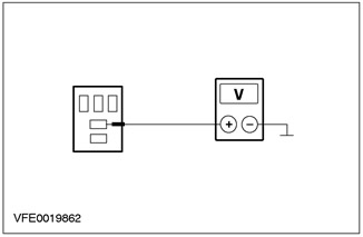
4 Measure the resistance between C1019 windshield wiper relay pin 2, CJB side, and "weight". |
|
• Is the resistance greater than 10 kΩ? |
|
|
→ Yes |
|
|
INSTALL a new common electronics module (GEM). CHECK the system is working properly. |
|
|
→ No |
|
|
LOCATE and REPAIR short circuit to "mass" in the electrical circuit between the windshield wiper relay and the common electronic module (GEM), using electrical diagrams. If necessary, INSTALL a new CJB. CHECK the system is working properly. |
|
|
L8: INSPECT CIRCUIT 8-KA19 (A) (WHITE/BLACK) AT WIPER/WASHER SWITCH AREA TO SHORT TO POWER SUPPLY |
|
|
1 Enter the OFF position. |
|
|
2 Disconnect Wiper/Washer Switch - C441. |
|
|
3 Drive the ON position. |
|
|
4 Measure the voltage between pin 10 of C441 wiper/washer switch circuit 8-KA19 (white/black), from the wiring side, and "weight". |
|
• Does the battery voltage register? |
|
|
→ Yes |
|
|
LOCATE and REPAIR short to power on circuit 8-KA19 (A) (white/black), between wiper/washer switch and common electronic module (GEM), using electrical diagrams. CHECK the system is working properly. |
|
|
→ No |
|
|
Go to L9 |
|
|
L9: CHECK WIPER/WASH SWITCH |
|
|
1 INSPECT the wiper/washer switch according to the component test instructions included with the wiring diagrams. |
|
|
• Is the switch OK? |
|
|
→ Yes |
|
|
INSTALL a new common electronics module (GEM). CHECK the system is working properly. |
|
|
→ No |
|
|
INSTALL a new wiper/washer switch. CHECK the system is working properly. |
|
|
L10: IDENTIFY THE STATE IN WHICH THE FAULT IS MANIFESTED |
|
|
1 Enter the OFF position. |
|
|
2 Disconnect the Windshield Wiper Motor - C848. |
|
|
3 Drive the ON position. |
|
|
4 Measure the voltage between pin 4 of the C848 windshield wiper motor circuit 32-KA11 (white/black), from the wiring side, and "weight". |
|
• Does the battery voltage register? |
|
|
→ Yes |
|
|
Go to L11 |
|
|
→ No |
|
|
INSTALL a new wiper motor. CHECK the system is working properly. |
|
|
L11: INSPECT WIPER/WASH SWITCH |
|
|
1 Enter the OFF position. |
|
|
2 Disconnect Wiper/Washer Switch - C441. |
|
|
3 INSPECT the wiper/washer switch according to the component test instructions included with the wiring diagrams. |
|
|
• Is the switch OK? |
|
|
→ Yes |
|
|
LOCATE and REPAIR short to power in the circuits connected to pin 8 of C441 wiper/washer switch using the electrical circuit diagrams. If necessary, INSTALL a new CJB. CHECK the system is working properly. |
|
|
→ No |
|
|
INSTALL a new wiper/washer switch. CHECK the system is working properly. |
|
|
L12: IDENTIFY THE STATE IN WHICH THE FAULT IS MANIFESTED |
|
|
1 Enter the OFF position. |
|
|
2 Disconnect the Rear Wiper Relay - C1018. |
|
|
3 Drive the ON position. |
|
|
4Check the rear window wiper. |
|
|
• Is the rear window wiper motor running continuously? |
|
|
→ Yes |
|
|
Go to L13 |
|
|
→ No |
|
|
INSPECT the rear window wiper relay in accordance with the component test instructions included with the wiring diagrams; if necessary, INSTALL the new element. If the relay is OK, Go to L14 |
|
|
L13: CHECK CIRCUIT 32-KA28 (WHITE/RED) ON THE SECTION OF THE ELECTRIC MOTOR OF THE REAR WINDOW CLEANER FOR A SHORT CIRCUIT TO THE POWER SUPPLY |
|
|
1 Enter the OFF position. |
|
|
2 Disconnect the Rear Wiper Motor - C971. |
|
|
3 Drive the ON position. |
|
|
4 Measure the voltage between pin 2 of the C971 rear window wiper motor circuit 32-KA28 (white/red), from the wiring side, and "weight". |
|
• Does the battery voltage register? |
|
|
→ Yes |
|
|
LOCATE and REPAIR short to power in the electrical circuit between the wiper relay and the wiper motor using the electrical circuit diagrams. If necessary, INSTALL a new CJB. CHECK the system is working properly. |
|
|
→ No |
|
|
INSTALL a new wiper motor. CHECK the system is working properly. |
|
|
L14: INSPECT REAR WIPER RELAY CONTROL CIRCUIT FOR A SHORT TO "MASS" |
|
|
1 Enter the OFF position. |
|
|
2 Disconnect the Common Electronic Module (GEM) - C105. |
|
|
3 Measure the resistance between C1018 rear window wiper relay pin 2, CJB side, and "weight". |
|
• Is the resistance greater than 10 kΩ? |
|
|
→ Yes |
|
|
INSTALL a new common electronics module (GEM). CHECK the system is working properly. |
|
|
→ No |
|
|
LOCATE and REPAIR short circuit to "mass" in the electrical circuit between the rear window wiper relay and the common electronic module (GEM), using electrical diagrams. If necessary, INSTALL a new CJB. CHECK the system is working properly. |
|
PINPOINT TEST M: HIGH/LOW SPEED CLEANING MODE DOES NOT FUNCTION PROPERLY (INTERMITTENT CLEANING MODE FUNCTIONING PROPERLY)
|
STATES |
DETAILS/RESULTS/ACTIONS |
|
M1: IDENTIFY THE STATE IN WHICH THE FAULT IS APPEARING. |
|
|
1 Drive the ON position. |
|
|
2 Switch on LOW SPEED and HIGH SPEED in sequence. |
|
|
3 Check the windshield wipers. |
|
|
• Is the wiper motor running in high speed? |
|
|
→ Yes |
|
|
Wipers do not operate in LOW SPEED MODE: INSPECT the wiper/washer switch according to the component test instructions included with the electrical diagrams; if necessary, INSTALL the new element. CHECK the system is working properly. |
|
|
Wiper motor running at high speed in LOW SPEED MODE: Go to M4 |
|
|
→ No |
|
|
Navigate to M2 |
|
|
M2: CHECK WINDSHIELD WIPER MOTOR VOLTAGE |
|
|
1 Enter the OFF position. |
|
|
2 Disconnect the Windshield Wiper Motor - C848. |
|
|
3 Drive the ON position. |
|
|
4 Turn on HIGH SPEED MODE. |
|
|
5 Measure the voltage between pin 4 C848 windshield wiper motor circuit 32-KA11 (white/black), from the wiring side, and "weight". |
|
• Does the battery voltage register? |
|
|
→ Yes |
|
|
INSTALL a new wiper motor. CHECK the system is working properly. |
|
|
→ No |
|
|
Go to M3 |
|
|
M3: CHECK WIPER/WASH SWITCH |
|
|
1 Enter the OFF position. |
|
|
2 Disconnect Wiper/Washer Switch - C441. |
|
|
3 INSPECT the wiper/washer switch according to the component test instructions included with the wiring diagrams. |
|
|
• Is the wiper/washer switch OK? |
|
|
→ Yes |
|
|
LOCATE and REPAIR open circuit 32-KA11 (white/black), between the wiper/washer switch and the wiper motor using the wiring diagrams. CHECK the system is working properly. |
|
|
→ No |
|
|
INSTALL a new wiper/washer switch. CHECK the system is working properly. |
|
|
M4: INSPECT WIPER/WASH SWITCH |
|
|
1 Disconnect Wiper/Washer Switch - C441. |
|
|
2 INSPECT the wiper/washer switch according to the component test instructions included with the electrical diagrams. |
|
|
• Is the wiper/washer switch OK? |
|
|
→ Yes |
|
|
INSPECT the windshield wiper motor according to the item test instructions included with this section. If necessary, INSTALL the new element. CHECK the system is working properly. |
|
|
→ No |
|
|
INSTALL a new wiper/washer switch. CHECK the system is working properly. |
|
PINPOINT TEST N: INTERMITTENT CLEANING MODE DOES NOT FUNCTION PROPERLY (HIGH/LOW SPEED CLEANING FUNCTIONING PROPERLY)
|
STATES |
DETAILS/RESULTS/ACTIONS |
|
N1: CHECK THE SYSTEM USING WDS |
|
|
1 Connect the diagnostic tool. |
|
|
2 Check the system using WDS. |
|
|
• Any DTCs registered (DTC)? |
|
|
→ Yes |
|
|
PROCESS DTCs according to WDS instructions. CLEAR fault memory and CHECK the system is operating correctly. |
|
|
→ No |
|
|
Go to N2 |
|
|
N2: INSPECT WIPER/WASH SWITCH |
|
|
1 Enter the OFF position. |
|
|
2 Disconnect Wiper/Washer Switch - C441. |
|
|
3 INSPECT the wiper/washer switch according to the component test instructions included with the wiring diagrams. |
|
|
• Is the wiper/washer switch OK? |
|
|
→ Yes |
|
|
Go to N3 |
|
|
→ No |
|
|
INSTALL a new wiper/washer switch. CHECK the system is working properly. |
|
|
N3: IDENTIFY THE STATE IN WHICH THE FAULT IS APPEARING. |
|
|
1 Connect Wiper/Washer Switch - C441. |
|
|
2 Determine the state in which the fault occurs. |
|
|
• Does the intermittent cleaning function not work? |
|
|
→ Yes |
|
|
Go to N4 |
|
|
→ No |
|
|
The intermittent cleaning function does not work correctly: Go to N9 |
|
|
The ADJUSTABLE intermittent cleaning function does not work properly: Go to N8 |
|
|
N4: IDENTIFY THE FAULTY STATE |
|
|
1 Drive the ON position. |
|
|
2 Enable SINGLE CLEAN MODE: |
|
|
3 Check the windshield wipers. |
|
|
• Windshield wipers return to non-working position: |
|
|
→ Yes |
|
|
Go to N5 |
|
|
→ No |
|
|
Go to P1 |
|
|
N5: CHECK WINDSHIELD WIPER RELAY VOLTAGE |
|
|
1 Enter the OFF position. |
|
|
2 Disconnect Windshield Wiper Relay - C1019. |
|
|
3 Drive the ON position. |
|
|
4 Measure the voltage between C1019 windshield wiper relay pin 1, CJB side, and "weight", and between pin 5, on the CJB side, and "weight". |
|
• Is the battery voltage recorded in both cases? |
|
|
→ Yes |
|
|
INSPECT the windshield wiper relay according to the component test instructions included with the electrical diagrams; if necessary, INSTALL the new element. If the relay is OK, Go to N6 |
|
|
→ No |
|
|
INSTALL a new central junction box (CJB). CHECK the system is working properly. |
|
|
N6: INSPECT WINDSHIELD WIPER RELAY CONTROL CIRCUIT |
|
|
NOTE: Turn off the windshield wipers. |
|
|
1 Enter the OFF position. |
|
|
2 Connect Windshield Wiper Relay - C1019. |
|
|
3 Disconnect the Common Electronic Module (GEM) - C105. |
|
|
4 Drive the ON position. |
|
|
5 Connect the connecting wire with fuse (10 A) between pin 21 C105 of the general electronic module (GEM), electrical circuit 91S-KA12A (black/white), from the wiring side, and "weight". |
|
6 Reconnect the wire and check the wipers. |
|
|
• Do the wipers operate and return to the off position? |
|
|
→ Yes |
|
|
Go to N7 |
|
|
→ No |
|
|
LOCATE and REPAIR open circuit between windshield wiper relay and C105 GEM pin 21 (GEM), using electrical diagrams. If necessary, INSTALL a new CJB. CHECK the system is working properly. |
|
|
N7: CHECK VOLTAGE ON COMMON ELECTRONIC MODULE (GEM) |
|
|
1 Enter the OFF position. |
|
|
2 Disconnect the Common Electronic Module (GEM) - C104. |
|
|
3 Drive the ON position. |
|
|
4 Enable INTERMITTENT CLEANING MODE. |
|
|
5 Measure the voltage between C104 pin 4 of the GEM (GEM), electrical circuit 8-KA19 (white/black), from the wiring side, and "weight". |
|
• Does the battery voltage register? |
|
|
→ Yes |
|
|
INSTALL a new common electronics module (GEM). CHECK the system is working properly. |
|
|
→ No |
|
|
LOCATE and REPAIR open circuit 8-KA19 (white/black), between wiper/washer switch and common electronic module (GEM), using electrical diagrams. CHECK the system is working properly. |
|
|
N8: CHECK VOLTAGE ON COMMON ELECTRONIC MODULE (GEM) |
|
|
1 Disconnect the Common Electronic Module (GEM) - C105. |
|
|
2 Drive the ON position. |
|
|
3 Turn ON INTERMITTENT CLEANING MODE. |
|
|
4 Measure the voltage between pin 4 of the C105 GEM (GEM), electrical circuit 8-KA18 (white), from the wiring side, and "weight". |
|
• Is voltage being registered? |
|
|
→ Yes |
|
|
INSTALL a new common electronics module (GEM). CHECK the system is working properly. |
|
|
→ No |
|
|
LOCATE and REPAIR open circuit 8-KA18 (white), between wiper/washer switch and common electronic module (GEM), using electrical diagrams. CHECK the system is working properly. |
|
|
N9: CHECK VOLTAGE ON COMMON ELECTRONIC MODULE (GEM) |
|
|
1 Disconnect the Common Electronic Module (GEM) - C103. |
|
|
2 Drive the ON position. |
|
|
3 Turn on SLOW SPEED CLEANING MODE. |
|
|
4Measure the voltage between pin 2 of C103 GEM (GEM), electrical circuit 32-KA9A (white/blue), from the wiring side, and "weight". |
|
• Does battery voltage register during the cleaning cycle? |
|
|
→ Yes |
|
|
INSTALL a new common electronics module (GEM). CHECK the system is working properly. |
|
|
→ No |
|
|
LOCATE and REPAIR open circuit 32-KA9A (white/blue), between connection S77 and common electronic module (GEM), using electrical diagrams. CHECK the system is working properly. |
|
PINPOINT TEST O: WASH AND CLEAN FUNCTION DOES NOT WORK
|
STATES |
DETAILS/RESULTS/ACTIONS |
|
O1: IDENTIFY THE STATE IN WHICH THE FAULT IS APPEARING. |
|
|
1 Activate the WINDSHIELD WASH function according to the REAR WASH mode. |
|
|
2 Determine the state in which the fault occurs. |
|
|
• The cleaning function does not work and the rinsing function works properly? |
|
|
→ Yes |
|
|
Go to O3 |
|
|
→ No |
|
|
Wash and clean function not working: Go to O2 |
|
|
O2: CHECK GROUND CONNECTION OF WIPER/WASH SWITCH |
|
|
1 Enter the OFF position. |
|
|
2 Disconnect Wiper/Washer Switch - C441. |
|
|
3 Measure the resistance between pin 3 of C441 wiper/washer switch circuit 31-KA19 (black), from the wiring side, and "weight". |
|
• Is the resistance less than 2 ohms? |
|
|
→ Yes |
|
|
INSTALL a new wiper/washer switch. CHECK the system is working properly. |
|
|
→ No |
|
|
LOCATE and REPAIR open circuit 31-KA19 (black), between the wiper/washer switch and "weight" G14 using the wiring diagrams. CHECK the system is working properly. |
|
|
O3: CHECK THE SYSTEM USING WDS |
|
|
1 Connect the diagnostic tool. |
|
|
2 Check the system using WDS. |
|
|
• Any DTCs registered (DTC)? |
|
|
→ Yes |
|
|
PROCESS DTCs according to WDS instructions. CLEAR fault memory and CHECK the system is operating correctly. |
|
|
→ No |
|
|
Go to O4 |
|
|
O4: CHECK WIPER/WASH SWITCH |
|
|
1 Enter the OFF position. |
|
|
2 Disconnect Wiper/Washer Switch - C441. |
|
|
3 Test the wiper/washer switch according to the component test instructions included with the wiring diagrams. |
|
|
• Is the switch OK? |
|
|
→ Yes |
|
|
Windshield wipe function not working: Go to O5 |
|
|
Rear window wiper does not work: Go to O6 |
|
|
→ No |
|
|
INSTALL a new wiper/washer switch. CHECK the system is working properly. |
|
|
O5: CHECK VOLTAGE ON COMMON ELECTRONIC MODULE (GEM) IN THE ELECTRICAL CIRCUIT 32-KA6A (WHITE/BLACK) |
|
|
1 Disconnect the Common Electronic Module (GEM) - C104. |
|
|
2 Drive the ON position. |
|
|
3 Turn on the WINDSHIELD WASHER. |
|
|
4 Measure the voltage between pin 5 of C104 of the general electronic module (GEM), electrical circuit 32-KA6A (white/black), from the wiring side, and "weight". |
|
• Does the battery voltage register? |
|
|
→ Yes |
|
|
INSTALL a new common electronics module (GEM). CHECK the system is working properly. |
|
|
→ No |
|
|
LOCATE and REPAIR open circuit 32-KA6 (A) (white/black), between wiper/washer switch and common electronic module (GEM), using electrical diagrams. CHECK the system is working properly. |
|
|
O6: CHECK VOLTAGE ON COMMON ELECTRONIC MODULE (GEM) IN THE ELECTRICAL CIRCUIT 33-KA6 (YELLOW/BLACK) |
|
|
1 Disconnect the Common Electronic Module (GEM) - C105. |
|
|
2 Drive the ON position. |
|
|
3 Turn on the REAR WASHER. |
|
|
4Measure the voltage between pin 2 of C105 GEM (GEM), electrical circuit 33-KA6 (yellow/black), from the wiring side, and "weight". |
|
• Does the battery voltage register? |
|
|
→ Yes |
|
|
INSTALL a new common electronics module (GEM). CHECK the system is working properly. |
|
|
→ No |
|
|
LOCATE and REPAIR open circuit 33-KA6 (yellow/black), between wiper/washer switch and common electronic module (GEM), using electrical diagrams. CHECK the system is working properly. |
|
PINPOINT TEST P: WIPERS DO NOT STOP IN CORRECT OFF POSITION
|
STATES |
DETAILS/RESULTS/ACTIONS |
|
P1: CHECK THE SYSTEM USING WDS |
|
|
1 Check the system using WDS. |
|
|
• Any DTCs registered (DTC)? |
|
|
→ Yes |
|
|
PROCESS DTCs according to WDS instructions. CLEAR fault memory and CHECK the system is operating correctly. |
|
|
→ No |
|
|
Go to P2 |
|
|
P2: IDENTIFY THE STATE IN WHICH THE FAULT IS APPEARING. |
|
|
1 Determine the state in which the fault occurs. |
|
|
• Does the windshield wipers' reset function not work? |
|
|
→ Yes |
|
|
Go to P3 |
|
|
→ No |
|
|
Rear window wiper does not stop in correct idle position: Go to P8 |
|
|
P3: CHECK WINDSHIELD WIPER MOTOR VOLTAGE |
|
|
1 Enter the OFF position. |
|
|
2 Disconnect the Windshield Wiper Motor - C848. |
|
|
3 Drive the ON position. |
|
|
4 Measure the voltage between C848 pin 3 of the windshield wiper motor, circuit 15-KA9 (green/red), from the wiring side, and "weight". |
|
• Does the battery voltage register? |
|
|
→ Yes |
|
|
Go to P4 |
|
|
→ No |
|
|
LOCATE and REPAIR open circuit 15-KA9 (green/red), between fuse F56 (CJB) and the windshield wiper motor using the wiring diagrams. CHECK the system is working properly. |
|
|
P4: INSPECT WINDSHIELD WIPER RELAY |
|
|
1 Enter the OFF position. |
|
|
2 Disconnect Windshield Wiper Relay - C1019. |
|
|
3 Test the windshield wiper relay according to the component test instructions included with the wiring diagrams. |
|
|
• Relay OK? |
|
|
→ Yes |
|
|
Go to P5 |
|
|
→ No |
|
|
INSTALL a new windshield wiper relay. CHECK the system is working properly. |
|
|
P5: INSPECT WINDSHIELD WIPER MOTOR |
|
|
1 INSPECT the windshield wiper motor according to the component test instructions included with this section. |
|
|
• Is the wiper motor OK? |
|
|
→ Yes |
|
|
Go to P6 |
|
|
→ No |
|
|
INSTALL a new wiper motor. CHECK the system is working properly. |
|
|
P6: CHECK WINDSHIELD WIPER MOTOR VOLTAGE |
|
|
1 Enter the OFF position. |
|
|
2 Connect the connection wire with fuse (10 A) to C1019 windshield wiper relay connector, between pin 4 and pin 5, CJB side. |
|
3 Drive the ON position. |
|
|
4 Measure the voltage between C848 pin 2 of the windshield wiper motor circuit 32-KA9 (white/blue), from the wiring side, and "weight". |
|
• Does the battery voltage register? |
|
|
→ Yes |
|
|
Go to P7 |
|
|
→ No |
|
|
LOCATE and REPAIR open circuit between windshield wiper relay and windshield wiper motor using the wiring diagrams. If necessary, INSTALL a new CJB. CHECK the system is working properly. |
|
|
P7: CHECK VOLTAGE AT WIPER/WASH SWITCH |
|
|
1 Enter the OFF position. |
|
|
2 Disconnect Wiper/Washer Switch - C441. |
|
|
3 Connect the connection wire with fuse (10 A) to C1019 windshield wiper relay connector, between pin 3 and pin 5, CJB side. |
|
4 Drive the ON position. |
|
|
5 Measure the voltage between pin 7 of C441 wiper/washer switch circuit 32-KA19 (A) (white/black), from the wiring side, and "weight". |
|
• Does the battery voltage register? |
|
|
→ Yes |
|
|
INSTALL a new wiper/washer switch. CHECK the system is working properly. |
|
|
→ No |
|
|
LOCATE and REPAIR the open circuit between the windshield wiper relay and C441 pin 7 of the wiper/washer switch using the electrical circuit diagrams. If necessary, INSTALL a new CJB. CHECK the system is working properly. |
|
|
P8: CHECK REAR WIPER MOTOR VOLTAGE |
|
|
1 Enter the OFF position. |
|
|
2 Disconnect the Rear Wiper Motor - C971. |
|
|
3 Drive the ON position. |
|
|
4 Measure the voltage between pin 1 of the C971 rear window wiper motor circuit 15-KA28 (green/brown), from the wiring side, and "weight". |
|
• Does the battery voltage register? |
|
|
→ Yes |
|
|
INSTALL a new wiper motor. CHECK the system is working properly. |
|
|
→ No |
|
|
LOCATE and REPAIR open circuit between fuse F43 (CJB) and pin 1 C971 rear wiper motor, using the wiring diagrams. If necessary, INSTALL a new CJB. CHECK the system is working properly. |
|
PINPOINT TEST Q: WASHER PUMP NOT WORKING
|
STATES |
DETAILS/RESULTS/ACTIONS |
|
Q1: IDENTIFY THE STATE IN WHICH THE FAULT IS APPEARING. |
|
|
1 Determine the state in which the fault occurs. |
|
|
• Front and rear window washer not working? |
|
|
→ Yes |
|
|
Go to Q2 |
|
|
→ No |
|
|
Front or rear window: INSTALL a new wiper/washer switch. CHECK the system is working properly. |
|
|
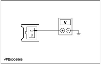
Q2: CHECK WASHER PUMP MOTOR VOLTAGE |
|
|
NOTE: Turn off the windshield wipers. |
|
|
1 Enter the OFF position. |
|
|
2 Disconnect the Windscreen Washer Pump Motor - C828. |
|
|
3 Drive the ON position. |
|
|
4 Measure the voltage between pin 1 of the C828 washer pump motor circuit 32-KA34 (white/black), from the wiring side, and "weight". |
|
• Does the battery voltage register? |
|
|
→ Yes |
|
|
Go to Q3 |
|
|
→ No |
|
|
LOCATE and REPAIR open circuit 32-KA34 (white/black), between the wiper/washer switch and the washer pump motor using the wiring diagrams. CHECK the system is working properly. |
|
|
Q3: CHECK WASHER PUMP MOTOR VOLTAGE |
|
|
1 Measure the voltage between pin 2 of the C828 washer pump motor circuit 33-KA34 (yellow/black), from the wiring side, and "weight". |
|
• Does the battery voltage register? |
|
|
→ Yes |
|
|
INSTALL a new washer pump motor. CHECK the system is working properly. |
|
|
→ No |
|
|
LOCATE and REPAIR open circuit 33-KA34 (yellow/black), between the wiper/washer switch and the washer pump motor using the wiring diagrams. CHECK the system is working properly. |
|
PINPOINT TEST R: HEADLIGHT WASHING FUNCTION DOES NOT WORK CORRECTLY
|
STATES |
DETAILS/RESULTS/ACTIONS |
|
R1: CHECK THE POWER SUPPLY OF THE HEADLIGHT WASHER RELAY |
|
|
1 Enter the OFF position. |
|
|
2 Disconnect Headlight Washer Relay - C1004. |
|
|
3 Drive the ON position. |
|
|
4 Measure the voltage between pin 2 of the C1004 headlight washer relay circuit 30-KA23 (red), from the BJB side, and "weight". |
|
• Does the battery voltage register? |
|
|
→ Yes |
|
|
Go to R4 |
|
|
→ No |
|
|
Go to R2 |
|
|
R2: CHECK FUSE F13 |
|
|
1 Enter the OFF position. |
|
|
2CHECK Fuse F13 (BJB). |
|
|
3 CHECK FUSE F13 (30 A) |
|
|
• Is the fuse good? |
|
|
→ Yes |
|
|
Go to R3 |
|
|
→ No |
|
|
Install new fuse F13 (30 A). If the fuse blows again, LOCATE and REPAIR the short circuit using the wiring diagrams. CHECK the system is working properly. |
|
|
R3: CHECK POWER SUPPLY OF FUSE F13 (BJB) |
|
|
1 Drive the ON position. |
|
|
2 Measure voltage between fuse F13 (BJB) And "weight". |
|
|
• Does the battery voltage register? |
|
|
→ Yes |
|
|
Go to R4 |
|
|
→ No |
|
|
Check out BJB. If necessary, INSTALL the new element. CHECK the system is working properly. |
|
|
R4: CHECK CONTROL CIRCUIT (WHEN THE HEADLIGHTS ARE ON) HEADLIGHT WASHER RELAY |
|
|
1 Enter the OFF position. |
|
|
2 Connect Fuse F13 (BJB). |
|
|
3 Drive the ON position. |
|
|
4 Set the light switch to "DIPPED HEADLIGHTS". |
|
|
5 Measure the voltage between pin 5 C1004 headlight washer relay circuit 15S-KA22 (green/brown), from the BJB side, and "weight". |
|
• Does the battery voltage register? |
|
|
→ Yes |
|
|
Go to R5 |
|
|
→ No |
|
|
LOCATE and REPAIR the open circuit between the light switch and the headlight washer relay using the wiring diagrams. CHECK the system is working properly. |
|
|
R5: CHECK GROUND CONNECTION OF HEADLIGHT WASHER RELAY |
|
|
1 Set the light switch to "TURNED OFF". |
|
|
2 Enter the OFF position. |
|
|
3 Measure the resistance between C1004 pin 1 of the headlight washer relay, circuit 31-KA22 (black), from the BJB side, and "weight". |
|
• Is the resistance less than 2 ohms? |
|
|
→ Yes |
|
|
Go to R6 |
|
|
→ No |
|
|
LOCATE and REPAIR open circuit between headlight washer relay and "weight" G37 using the wiring diagrams. CHECK the system is working properly. |
|
|
R6: CHECK CONTROL CIRCUIT (WASHING ON), TO THE HEADLIGHT WASHER RELAY |
|
|
1 Enter the OFF position. |
|
|
2 Operate the WINDSHIELD WASHER during measurement. |
|
|
3 Measure the resistance between pin 3 of the C1004 headlight washer relay, circuit 32-KA22 (white/red) And "weight". |
|
• Is the resistance less than 2 ohms? |
|
|
→ Yes |
|
|
Go to R7 |
|
|
→ No |
|
|
LOCATE and REPAIR open circuit between C1004 headlamp washer relay pin 3 and S128 connection using the wiring diagrams. CHECK the system is working properly. |
|
|
R7: INSPECT HEADLIGHT WASH PUMP. |
|
|
1 Connect Headlight Washer Relay - C1004. |
|
|
2 Disconnect the headlight washer pump motor - C745. |
|
|
3 Drive the ON position. |
|
|
4 Set the light switch to "DIPPED HEADLIGHTS". |
|
|
5 Operate the WINDSHIELD WASHER during measurement. |
|
|
6 Measure the voltage between C745 pin 1 of the headlight washer pump motor circuit 15S-KA21 (green/yellow), from the wiring side, and "weight". |
|
• Does the battery voltage register? |
|
|
→ Yes |
|
|
Go to R8 |
|
|
→ No |
|
|
LOCATE and REPAIR open circuit between C1004 headlamp washer relay pin 4 and headlamp washer pump motor using the electrical circuit diagrams. CHECK the system is working properly. |
|
|
R8: CHECK HEADLIGHT WASH PUMP GROUND CONNECTION |
|
|
1 Enter the OFF position. |
|
|
2 Measure the resistance between pin 2 of C745 headlight washer pump motor circuit 31-KA21 (black), from the wiring side, and "weight". |
|
• Is the resistance less than 2 ohms? |
|
|
→ Yes |
|
|
INSPECT headlight washer pump motor. If necessary, INSTALL the new element. CHECK the system is working properly. |
|
|
→ No |
|
|
LOCATE and REPAIR open circuit between headlight washer pump motor and "weight" G37 using the wiring diagrams. CHECK the system is working properly. |
|
Visitor comments