|
STATES |
DETAILS/RESULTS/ACTIONS |
|
A1: CHECK FUSE F55 |
|
|
1 Enter the OFF position. |
|
|
2 CHECK Fuse F55 (CJB). |
|
|
3 CHECK FUSE F55 (20 A) |
|
|
• Is the fuse good? |
|
|
→ Yes |
|
|
Go to A2 |
|
|
→ No |
|
|
Install new fuse F55 (20 A). If the fuse blows again, LOCATE and REPAIR the short circuit using the wiring diagrams. CHECK the system is working properly. |
|
|
A2: CHECK POWER SUPPLY OF F55 FUSE |
|
|
1 Connect Fuse F55 (CJB). |
|
|
2 Drive the ON position. |
|
|
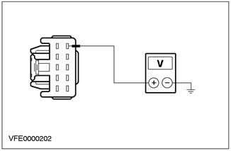
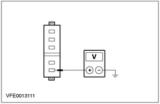
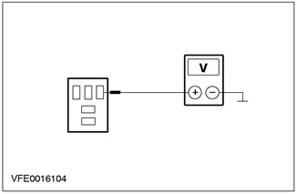
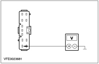
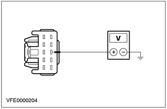
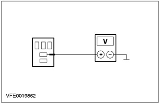
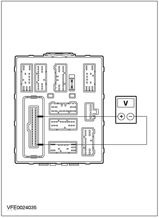
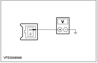
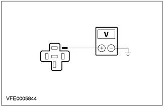
3 Measure the voltage between fuse F55 and "weight ". |
|
|
• Does the battery voltage register? |
|
|
→ Yes |
|
|
Vehicles with rear window wipers: Go to A3 |
|
|
Vehicles without rear window wipers: Go to A5 |
|
|
→ No |
|
|
Check CJB If necessary, INSTALL a new element. CHECK the system is working properly. |
|
|
A3: CHECK F43 FUSE |
|
|
1 Enter the OFF position. |
|
|
2 CHECK Fuse F43 (CJB). |
|
|
3 CHECK FUSE F43 (15 A) |
|
|
• Is the fuse good? |
|
|
→ Yes |
|
|
Go to A4 |
|
|
→ No |
|
|
Install new fuse F43 (15 A). If the fuse blows again, LOCATE and REPAIR the short circuit using the wiring diagrams. CHECK the system is working properly. |
|
|
A4: CHECK POWER SUPPLY OF F43 FUSE |
|
|
1 Connect Fuse F43 (CJB). |
|
|
2 Drive the ON position. |
|
|
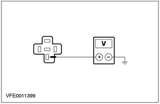
3 Measure the voltage between fuse F43 and "weight". |
|
|
• Does the battery voltage register? |
|
|
→ Yes |
|
|
Go to A5 |
|
|
→ No |
|
|
Check CJB If necessary, INSTALL a new element. CHECK the system is working properly. |
|
|
A5: CHECK POWER SUPPLY OF WIPER/WASH SWITCH |
|
|
1 TEST the system using WDS. If any DTCs are set, deal with those codes. CHECK the system is working properly. If the system fails again, perform the following test steps. |
|
|
2 Enter the OFF position. |
|
|
3 Disconnect the Wiper/Washer Switch - C441. |
|
|
4 Drive the ON position. |
|
|
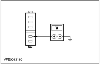
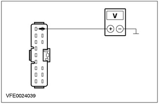
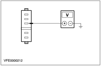
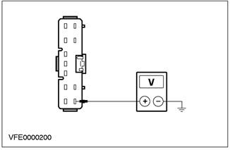
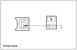
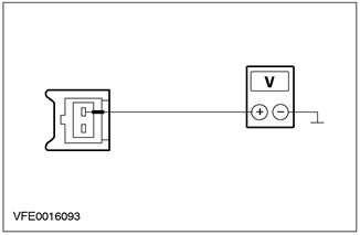
5 Measure the voltage between pin 6 of C441 wiper/washer switch circuit 15-KA19 (green/orange), from the wiring side, and "weight". |
|
• Does the battery voltage register? |
|
|
→ Yes |
|
|
Windshield wipers not working: Go to A6 |
|
|
Rear window wipers not working: Go to A8 |
|
|
→ No |
|
|
REPAIR short circuit (I) between the wiper/washer switch and C17 CJB pin 1 using the wiring diagrams. CHECK the system is working properly. |
|
|
A6: CHECK LOW SPEED POWER SUPPLY TO WINDSCREEN WIPER MOTOR |
|
|
1 Enter the OFF position. |
|
|
2 Connect Wiper/Washer Switch - C441. |
|
|
3 Disconnect the Windshield Wiper Motor - C848. |
|
|
4 Drive the ON position. |
|
|
5 Set the wiper/washer switch to "LOW SPEED CLEANING". |
|
|
6 Measure the voltage between pin 5 of the C848 windshield wiper motor circuit 32-KA10 (white/green), from the wiring side, and "weight". |
|
• Does the battery voltage register? |
|
|
→ Yes |
|
|
Go to A7 |
|
|
→ No |
|
|
INSPECT the wiper/washer switch according to the item test instructions included with this section. If necessary, INSTALL the new element. CHECK the system is working properly. |
|
|
A7: CHECK WINDSHIELD WIPER MOTOR GROUND CONNECTION |
|
|
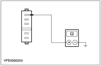
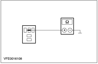
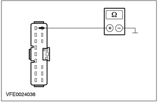
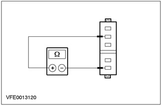
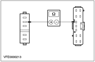
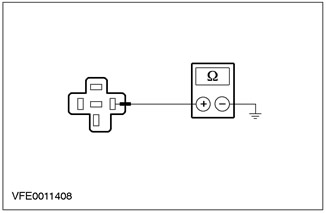
1 Measure the resistance between C848 windshield wiper motor pin 1, circuit 31-KA9 (black), from the wiring side, and "weight". |
|
• Is the resistance less than 2 ohms? |
|
|
→ Yes |
|
|
INSPECT the windshield wiper motor according to the item test instructions included with this section. If necessary, INSTALL the new element. CHECK the system is working properly. |
|
|
→ No |
|
|
REPAIR short circuit (I) between the windshield wiper motor and "weight" G37 using the wiring diagrams. CHECK the system is working properly. |
|
|
A8: CHECK GROUND CONNECTION OF REAR WIPER MOTOR |
|
|
1 Enter the OFF position. |
|
|
2 CHECK the ground connection of the rear window wiper motor housing. |
|
|
• Is the ground connection correct? |
|
|
→ Yes |
|
|
Go to A9 |
|
|
→ No |
|
|
REPAIR the ground connection between the rear window wiper motor housing and "weight". CHECK the system is working properly. |
|
|
A9: CHECK REAR WIPER RELAY POWER SUPPLY |
|
|
1 Connect Wiper/Washer Switch - C441. |
|
|
2 Disconnect the Rear Wiper Relay - C1018. |
|
|
3 Drive the ON position. |
|
|
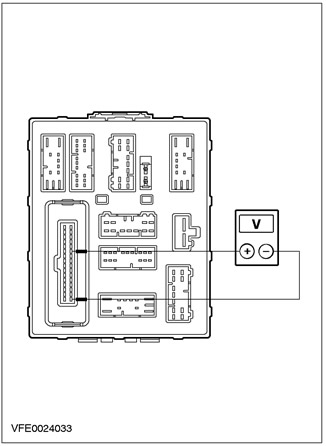
4 Measure the voltage between pin 5 of the C1018 rear window wiper relay and "weight". |
|
• Does the battery voltage register? |
|
|
→ Yes |
|
|
Go to A10 |
|
|
→ No |
|
|
Check CJB If necessary, INSTALL a new element. CHECK the system is working properly. |
|
|
A10: INSPECT REAR WIPER RELAY CONTROL CIRCUIT |
|
|
1 Measure the voltage between pin 1 of the C1018 rear window wiper relay and "weight". |
|
• Does the battery voltage register? |
|
|
→ Yes |
|
|
Go to A11 |
|
|
→ No |
|
|
Check CJB If necessary, INSTALL a new element. CHECK the system is working properly. |
|
|
A11: INSPECT REAR WIPER RELAY |
|
|
1 Test the rear window wiper relay according to the item test instructions included with this section. |
|
|
• Relay OK? |
|
|
→ Yes |
|
|
Go to A12 |
|
|
→ No |
|
|
INSTALL a new rear window wiper relay. CHECK the system is working properly. |
|
|
A12: CHECK CJB |
|
|
1 Enter the OFF position. |
|
|
2 Connect Rear Wiper Relay - C1018. |
|
|
3 Disconnect the central connection box (CJB).- C14. |
|
|
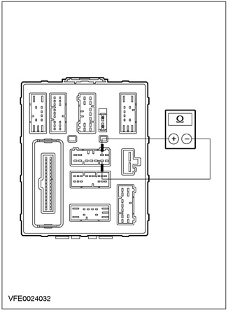
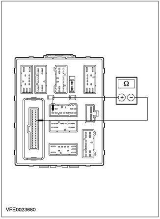
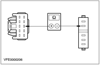
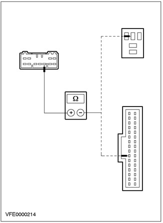
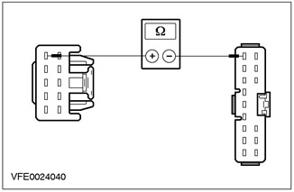
4 Measure the resistance at the C14 CJB connector, between pin 3 and pin 10, on the CJB side. |
|
• Is the resistance less than 2 ohms? |
|
|
→ Yes |
|
|
Go to A13 |
|
|
→ No |
|
|
Check CJB If necessary, INSTALL a new element. CHECK the system is working properly. |
|
|
A13: INSPECT GROUND CIRCUIT OF REAR WIPER RELAY |
|
|
1 Enter the OFF position. |
|
|
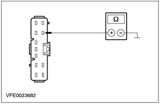
2 Measure the resistance between C14 CJB pin 3 on the wiring side, and "weight". |
|
• Is the resistance less than 2 ohms? |
|
|
→ Yes |
|
|
Go to A14 |
|
|
→ No |
|
|
REPAIR short circuit (I) between pin 3 C14 CJB and "weight" G14 using the wiring diagrams. CHECK the system is working properly. |
|
|
A14: INSPECT REAR WIPER CONTROL CIRCUIT TO CTM |
|
|
1 Drive the ON position. |
|
|
2 Set the wiper/washer switch to "REAR WINDOW WIPER". |
|

|
3 Measure the voltage between pin 5 C14 CJB, circuit 32-KA35 (white/red), from the wiring side, and "weight". |
|
• Does the battery voltage register? |
|
|
→ Yes |
|
|
Go to A16 |
|
|
→ No |
|
|
Go to A15 |
|
|
A15: CHECK WIPER/WASH SWITCH |
|
|
1 Enter the OFF position. |
|
|
2 Disconnect Wiper/Washer Switch - C441. |
|
|
3 Connect the jumper wire to connector C441 of the wiper/washer switch, between pin 6, circuit 15-KA19 (green/orange) and pin 5, electrical circuit 32-KA35 (white/red), from the side of the electrical wiring. |
|
4 Drive the ON position. |
|
|
5 Measure the voltage between pin 5 C14 CJB, circuit 32-KA35 (white/red), from the wiring side, and "weight". |
|
• Does the battery voltage register? |
|
|
→ Yes |
|
|
INSPECT the wiper/washer switch according to the item test instructions included with this section. If necessary, INSTALL the new element. CHECK the system is working properly. |
|
|
→ No |
|
|
REPAIR short circuit (I) between C14 CJB pin 5 and the wiper/washer switch using the wiring diagrams. CHECK the system is working properly. |
|
|
A16: CHECK CJB |
|
|
1 Enter the OFF position. |
|
|
2 Disconnect the Central Timer Module (CTM) - C1000. |
|
|
3 Measure the resistance at the CJB between C14 pin 5 and C1000 CTM pin 28. |
|
• Is the resistance less than 2 ohms? |
|
|
→ Yes |
|
|
Go to A17 |
|
|
→ No |
|
|
Check CJB If necessary, INSTALL a new element. CHECK the system is working properly. |
|
|
A17: INSPECT ELECTRICAL CIRCUIT TO REAR WIPER MOTOR |
|
|
1Connect Central Junction Box (CJB) - C14. |
|
|
2 Connect the Central Timer Module (CTM) - C1000. |
|
|
3 Disconnect the Rear Wiper Motor - C971. |
|
|
4 Drive the ON position. |
|
|
5 Measure the voltage between pin 1 of the C971 rear window wiper motor circuit 15-KA28 (green/blue), from the wiring side, and "weight". |
|
• Does the battery voltage register? |
|
|
→ Yes |
|
|
Go to A18 |
|
|
→ No |
|
|
REPAIR short circuit (I) between the wiper/washer switch and the rear window wiper motor using the wiring diagrams. CHECK the system is working properly. |
|
|
A18: INSPECT WIPER OFF CIRCUIT TO REAR WIPER MOTOR |
|
|
1 Set the wiper/washer switch to "REAR WINDOW WIPER". |
|
|
2 Measure the voltage between pin 2 of the C971 rear window wiper motor circuit 32-KA28 (white/red), from the wiring side, and "weight". |
|
• Does the battery voltage register? |
|
|
→ Yes |
|
|
INSPECT the rear window wiper motor according to the Element Inspection instructions included with this section, INSTALL a new element if necessary. CHECK the system is working properly. |
|
|
→ No |
|
|
REPAIR short circuit (I) between the wiper/washer switch and the rear window wiper motor using the wiring diagrams. CHECK the system is working properly. |
|
PINPOINT TEST B: WIPERS WORK CONTINUOUSLY
|
STATES |
DETAILS/RESULTS/ACTIONS |
|
B1: CHECK THE SYSTEM USING WDS |
|
|
1 Check the system using WDS. |
|
|
• Are any DTCs registered? |
|
|
→ Yes |
|
|
Process these codes. CHECK the system is working properly. |
|
|
→ No |
|
|
Rear window wipers running continuously: Go to B8 |
|
|
Windshield wipers running continuously: Go to B2 |
|
|
B2: CHECK FAULTY STATE |
|
|
1 Enter the OFF position. |
|
|
2 Disconnect Windshield Wiper Relay - C1019. |
|
|
3 Drive the ON position. |
|
|
4Check the windshield wipers. |
|
|
• Are the windshield wipers running continuously? |
|
|
→ Yes |
|
|
Go to B6 |
|
|
→ No |
|
|
Go to B3 |
|
|
B3: INSPECT WINDSHIELD WIPER RELAY CONTROL CIRCUIT FOR A SHORT TO "MASS" |
|
|
1 Enter the OFF position. |
|

|
2 Measure the resistance between C1019 pin 2 of the windshield wiper relay and "weight". |
|
• Is the resistance greater than 10 kΩ? |
|
|
→ Yes |
|
|
Go to B4 |
|
|
→ No |
|
|
Check CJB If necessary, INSTALL a new element. CHECK the system is working properly. |
|
|
B4: INSPECT WINDSHIELD WIPER RELAY |
|
|
1 INSPECT the windshield wiper relay according to the item test instructions included with this section. |
|
|
• Relay OK? |
|
|
→ Yes |
|
|
Go to B5 |
|
|
→ No |
|
|
INSTALL a new windshield wiper relay. CHECK the system is working properly. |
|
|
B5: CHECK WIPER/WASHER SWITCH FUNCTIONS CORRECTLY |
|
|
1 Enter the OFF position. |
|
|
2 Disconnect Wiper/Washer Switch - C441. |
|
|
3 INSPECT the wiper/washer switch according to the component test instructions included with this section. |
|
|
• Is the switch OK? |
|
|
→ Yes |
|
|
REPAIR the short to power in the circuit connected to pin 10 C441 of the wiper/washer switch using the wiring diagrams. CHECK the system is working properly. |
|
|
→ No |
|
|
INSTALL a new wiper/washer switch. CHECK the system is working properly. |
|
|
B6: DETERMINE STATE |
|
|
1 Enter the OFF position. |
|
|
2 Connect Windshield Wiper Relay - C1019. |
|
|
3 Disconnect the Wiper/Washer Switch - C441. |
|
|
4 Drive the ON position. |
|
|
5 Check the windshield wipers. |
|
|
• Windshield wipers on continuously? |
|
|
→ Yes |
|
|
Go to B7 |
|
|
→ No |
|
|
INSPECT the wiper/washer switch according to the item test instructions included with this section. If necessary, INSTALL the new element. CHECK the system is working properly. |
|
|
B7: INSPECT HIGH SPEED CLEANING CIRCUIT TO WINDSHIELD WIPER MOTOR |
|
|
1 Measure the voltage between pin 8 of C441 wiper/washer switch circuit 32-KA11 (white/black), from the wiring side, and "weight". |
|
• Does the battery voltage register? |
|
|
→ Yes |
|
|
REPAIR the short to power in the circuit connected to pin 8 C441 of the wiper/washer switch using the wiring diagrams. CHECK the system is working properly. |
|
|
→ No |
|
|
INSPECT the windshield wiper motor according to the item test instructions included with this section. If necessary, INSTALL the new element. CHECK the system is working properly. |
|
|
B8: INSPECT REAR WIPER RELAY |
|
|
1 Enter the OFF position. |
|
|
2 Disconnect the Rear Wiper Relay - C1018. |
|
|
3 Drive the ON position. |
|
|
4Check the windshield wipers. |
|
|
• Windshield wipers on continuously? |
|
|
→ Yes |
|
|
Go to B9 |
|
|
→ No |
|
|
Go to B10 |
|
|
B9: CHECK WIPER/WASH SWITCH |
|
|
1 Enter the OFF position. |
|
|
2 Connect Rear Wiper Relay - C1018. |
|
|
3 Disconnect the Wiper/Washer Switch - C441. |
|
|
4 Drive the ON position. |
|
|
5 Check the windshield wipers. |
|
|
• Windshield wipers on continuously? |
|
|
→ Yes |
|
|
INSPECT the rear window wiper motor according to the item test instructions included with this section. If necessary, INSTALL the new element. CHECK the system is working properly. |
|
|
→ No |
|
|
INSPECT the wiper/washer switch according to the item test instructions included with this section. If necessary, INSTALL the new element. CHECK the system is working properly. |
|
|
B10: CHECK REAR WIPER RELAY FOR PROPER OPERATION |
|
|
1 INSPECT the rear window wiper relay according to the item test instructions included with this section. |
|
|
• Relay OK? |
|
|
→ Yes |
|
|
Go to B11 |
|
|
→ No |
|
|
INSTALL a new rear window wiper relay. CHECK the system is working properly. |
|
|
B11: INSPECT REAR WIPER RELAY CONTROL CIRCUIT FOR A SHORT TO "MASS" |
|
|
1 Enter the OFF position. |
|
|
2 Measure the resistance between pin 2 of the C1018 rear window wiper relay and "weight". |
|
• Is the resistance greater than 10 kΩ? |
|
|
→ Yes |
|
|
INSPECT the wiper/washer switch according to the item test instructions included with this section. If necessary, INSTALL the new element. CHECK the system is working properly. |
|
|
→ No |
|
|
Check CJB If necessary, INSTALL a new element. CHECK the system is working properly. |
|
PINPOINT TEST C: LOW/HIGH SPEED WIPERS DO NOT FUNCTION PROPERLY (INTERMITTENT WIPER MODE FUNCTIONING PROPERLY)
|
STATES |
DETAILS/RESULTS/ACTIONS |
|
C1: INSPECT LOW SPEED CLEANING CIRCUIT TO WINDSHIELD WIPER MOTOR |
|
|
1 TEST the system using WDS. If any DTCs are set, deal with those codes. CHECK the system is working properly. If the system fails again, perform the following test steps. |
|
|
2 Enter the OFF position. |
|
|
3 Disconnect the Windshield Wiper Motor - C848. |
|
|
4 Drive the ON position. |
|
|
5 Set the wiper/washer switch to "LOW SPEED CLEANING". |
|

|
6 Measure the voltage between pin 5 of the C848 windshield wiper motor circuit 32-KA10 (white/green), And "weight". |
|
• Does the battery voltage register? |
|
|
→ Yes |
|
|
Go to C2 |
|
|
→ No |
|
|
INSPECT the wiper/washer switch according to the item test instructions included with this section. If necessary, INSTALL the new element. CHECK the system is working properly. |
|
|
C2: INSPECT POWER SUPPLY TO HIGH SPEED CLEANING CIRCUIT TO WINDSHIELD WIPER MOTOR |
|
|
1 Set the wiper/washer switch to "HIGH SPEED CLEANING". |
|
|
2 Measure the voltage between pin 4 C848 windshield wiper motor circuit 32-KA11 (white/black), from the wiring side, and "weight". |
|
• Does the battery voltage register? |
|
|
→ Yes |
|
|
INSPECT the windshield wiper motor according to the item test instructions included with this section. If necessary, INSTALL the new element. CHECK the system is working properly. |
|
|
→ No |
|
|
Go to C3 |
|
|
C3: INSPECT HIGH SPEED CLEANING CIRCUIT TO WINDSHIELD WIPER MOTOR |
|
|
1 Enter the OFF position. |
|
|
2 Disconnect Wiper/Washer Switch - C441. |
|
|
3 Measure the resistance between pin 8 of C441 wiper/washer switch circuit 32-KA11 (white/black), wiring side, and pin 4 C848 windshield wiper motor, circuit 32-KA11 (white/black), from the side of the electrical wiring. |
|
• Is the resistance less than 2 ohms? |
|
|
→ Yes |
|
|
Go to C4 |
|
|
→ No |
|
|
REPAIR short circuit (I) between the wiper/washer switch and the windshield wiper motor using the wiring diagrams. CHECK the system is working properly. |
|
|
C4: CHECK FOR PROPER FUNCTIONING OF WINDSCREEN WIPER ELECTRIC |
|
|
1 Connect the Windshield Wiper Motor - C848. |
|

|
2 Connect the jumper wire to connector C441 of the wiper/washer switch, between pin 6, circuit 15-KA19 (green/orange), and pin 8, electrical circuit 32-KA11 (white/black), from the side of the electrical wiring. |
|
3 Drive the ON position. |
|
|
4 Check the operation of the windshield wipers. |
|
|
• The windshield wiper motor is functioning properly (in high-speed cleaning mode)? |
|
|
→ Yes |
|
|
INSPECT the wiper/washer switch according to the item test instructions included with this section. If necessary, INSTALL the new element. CHECK the system is working properly. |
|
|
→ No |
|
|
INSPECT the windshield wiper motor according to the item test instructions included with this section. If necessary, INSTALL the new element. CHECK the system is working properly. |
|
PINPOINT TEST D: INTERMEDIATE WIPERS DO NOT FUNCTION PROPERLY (LOW/HIGH SPEED WIPERS FUNCTION PROPERLY)
|
STATES |
DETAILS/RESULTS/ACTIONS |
|
D1: INSPECT CONTROL CIRCUIT TO WINDSHIELD WIPER RELAY |
|
|
1 Enter the OFF position. |
|
|
2 Disconnect Windshield Wiper Relay - C1019. |
|
|
3 Drive the ON position. |
|

|
4 Measure the voltage between C1019 pin 1 of the windshield wiper relay and "weight". |
|
• Does the battery voltage register? |
|
|
→ Yes |
|
|
Go to D2 |
|
|
→ No |
|
|
Check CJB If necessary, INSTALL a new element. CHECK the system is working properly. |
|
|
D2: CHECK WINDSHIELD WIPER RELAY POWER |
|
|
1 Measure the voltage between C1019 pin 5 of the windshield wiper relay and "weight". |
|
• Does the battery voltage register? |
|
|
→ Yes |
|
|
Go to D3 |
|
|
→ No |
|
|
Check CJB If necessary, INSTALL a new element. CHECK the system is working properly. |
|
|
D3: INSPECT WINDSHIELD WIPER RELAY CONTROL CIRCUIT FOR SHORT TO POWER SUPPLY |
|

|
1 Measure the voltage between C1019 pin 2 of the windshield wiper relay and "weight". |
|
• Does the battery voltage register? |
|
|
→ Yes |
|
|
Check CJB If necessary, INSTALL a new element. CHECK the system is working properly. |
|
|
→ No |
|
|
Go to D4 |
|
|
D4: CHECK FOR PROPER FUNCTIONING OF WINDSCREEN WIPER RELAY |
|
|
1 Enter the OFF position. |
|
|
2 INSPECT the windshield wiper relays according to the item test instructions included with this section. |
|
|
• Relay OK? |
|
|
→ Yes |
|
|
Go to D5 |
|
|
→ No |
|
|
CHECK the system is working properly. CHECK the system is working properly. |
|
|
D5: CHECK THE POWER SUPPLY OF THE INTERMITTENT CLEANING MODE TO THE CTM |
|
|
1 Connect Windshield Wiper Relay - C1019. |
|
|
2 CHECK the system using WDS. If any DTCs are set, deal with those codes. CHECK the system is working properly. If the system fails again, perform the following test steps. |
|
|
3 Enter the OFF position. |
|
|
4 Disconnect the central connection box (CJB) - C15. |
|
|
5 Drive the ON position. |
|
|
6 Set the wiper/washer switch to "INTERMITTENT CLEANING". |
|

|
7 Measure the voltage between pin 6 C15 CJB, circuit 8-KA19 (white/black), from the wiring side, and "weight". |
|
• Does the battery voltage register? |
|
|
→ Yes |
|
|
Check CJB If necessary, INSTALL a new element. CHECK the system is working properly. |
|
|
→ No |
|
|
Go to D6 |
|
|
D6: CHECK WIPER/WASHER SWITCH FUNCTIONS CORRECTLY |
|
|
1 Enter the OFF position. |
|
|
2 Disconnect Wiper/Washer Switch - C441. |
|
|
3 INSPECT the wiper/washer switch according to the component test instructions included with this section. |
|
|
• Is the switch OK? |
|
|
→ Yes |
|
|
With variable speed intermittent cleaning mode: Go to D7 |
|
|
Without variable speed intermittent cleaning mode: REPAIR short circuit (I) between C15 CJB pin 6 and the wiper/washer switch using the wiring diagrams. CHECK the system is working properly. |
|
|
→ No |
|
|
INSTALL a new wiper/washer switch. CHECK the system is working properly. |
|
|
D7: INSPECT CONTROL CIRCUIT 8-KA18 (WHITE), TO CTM TO OPEN |
|
|
1Connect Central Junction Box (CJB) - C15. |
|
|
2 Disconnect the central connection box (CJB) - C11. |
|

|
3 Measure the resistance between pin 15 C11 CJB, circuit 8-KA18 (white), on the wiring side, and pin 1 C441 of the wiper/washer switch, circuit 8-KA18 (white), from the side of the electrical wiring. |
|
• Is the resistance less than 2 ohms? |
|
|
→ Yes |
|
|
Go to D8 |
|
|
→ No |
|
|
REPAIR short circuit (I) between pin 15 C11 CJB and the wiper/washer switch using the wiring diagrams. CHECK the system is working properly. |
|
|
D8: INSPECT CONTROL CIRCUIT 8-KA18 (WHITE), TO CTM, SHORT TO POWER SUPPLY |
|
|
1 Connect Wiper/Washer Switch - C441. |
|
|
2 Drive the ON position. |
|
|
3 Set the wiper/washer switch to "TURNED OFF". |
|
|
4 Measure the voltage between pin 15 C11 CJB, circuit 8-KA18 (white), from the wiring side, and "weight". |
|
• Does the battery voltage register? |
|
|
→ Yes |
|
|
REPAIR the short to power in the circuit connected to pin 1 of the wiper/washer switch C441 using the wiring diagrams. CHECK the system is working properly. |
|
|
→ No |
|
|
Go to D9 |
|
|
D9: INSPECT CONTROL CIRCUIT 8-KA18 (WHITE), DIRECTIONAL TO CTM FOR A SHORT CIRCUIT ON "MASS". |
|
|
1 Enter the OFF position. |
|
|
2 Measure the resistance between pin 15 C11 CJB, circuit 8-KA18 (white), from the wiring side, and "weight". |
|
• Is the resistance greater than 10 kΩ? |
|
|
→ Yes |
|
|
Check CJB If necessary, INSTALL a new element. CHECK the system is working properly. |
|
|
→ No |
|
|
REPAIR short circuit "mass" electrical circuit (to her), connected to pin 1 C441 of the wiper/washer switch using the wiring diagrams. CHECK the system is working properly. |
|
PINPOINT TEST E: WASH AND CLEAN FUNCTION DOES NOT WORK
|
STATES |
DETAILS/RESULTS/ACTIONS |
|
E1: TEST THE SYSTEM USING WDS. |
|
|
1 TEST the system using WDS. |
|
|
• Are any DTCs registered? |
|
|
→ Yes |
|
|
Process these codes. CHECK the system is working properly. |
|
|
→ No |
|
|
Go to E2 |
|
|
E2: INSPECT CLEAN AND WASH ELECTRICAL CIRCUIT TO CTM |
|
|
1 Enter the OFF position. |
|
|
2 Disconnect the Central Timer Module (CTM) - C1000. |
|
|
3 Drive the ON position. |
|
|
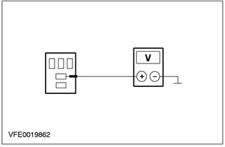
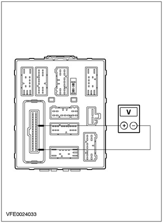
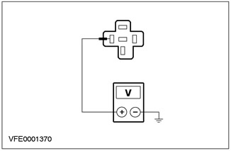
4 Measure the voltage at the C1000 CTM connector, between pin 27 and pin 17. |
|
• Does the battery voltage register? |
|
|
→ Yes |
|
|
Go to E4 |
|
|
→ No |
|
|
Go to E3 |
|
|
E3: CHECK WIPER/WASH SWITCH FUNCTIONING CORRECTLY |
|
|
1 Enter the OFF position. |
|
|
2 Disconnect Wiper/Washer Switch - C441. |
|
|
3 INSPECT the wiper/washer switch according to the component test instructions included with this section. |
|
|
• Is the switch OK? |
|
|
→ Yes |
|
|
REPAIR the open circuit between C1000 CTM pin 27 and the wiper/washer switch using the wiring diagrams. CHECK the system is working properly. |
|
|
→ No |
|
|
INSTALL a new wiper/washer switch. CHECK the system is working properly. |
|
|
E4: CHECK WIPER/WASH SWITCH FUNCTIONING CORRECTLY |
|
|
1 Enter the OFF position. |
|
|
2 Disconnect Wiper/Washer Switch - C441. |
|
|
3 INSPECT the wiper/washer switch according to the component test instructions included with this section. |
|
|
• Is the switch OK? |
|
|
→ Yes |
|
|
Go to E5 |
|
|
→ No |
|
|
INSTALL a new wiper/washer switch. CHECK the system is working properly. |
|
|
E5: INSPECT WASH AND WASH CIRCUIT TO WIPER/WASHER SWITCH |
|
|
1 Connect Wiper/Washer Switch - C441. |
|
|
2 Drive the ON position. |
|
|
3 Measure the voltage at the C1000 CTM connector, between pin 29 and pin 17. |
|
• Does the battery voltage register? |
|
|
→ Yes |
|
|
REPAIR open circuit 31-KA19 (black), between the wiper/washer switch and "weight" G14 using the wiring diagrams. CHECK the system is working properly. |
|
|
→ No |
|
|
REPAIR open circuit 32-KA6 (white/black), between the wiper/washer switch and connection S14, using the wiring diagrams. CHECK the system is working properly. |
|
PINPOINT TEST F: WIPERS DO NOT STOP IN CORRECT OFF POSITION
|
STATES |
DETAILS/RESULTS/ACTIONS |
|
F1: DETERMINE STATE |
|
|
1 Determine the equipment of the car. |
|
|
• Is the vehicle equipped with rear window wipers? |
|
|
→ Yes |
|
|
Go to F2 |
|
|
→ No |
|
|
Go to F3 |
|
|
F2: IDENTIFY THE STATE IN WHICH THE FAULT IS APPEARING. |
|
|
1 Drive the ON position. |
|
|
2 Set the wiper/washer switch to "REAR WINDOW WIPER" and in position "TURNED OFF". |
|
|
3 Check that the windshield wipers are not in use. |
|
|
• Do the rear window wipers stop in the correct off position? |
|
|
→ Yes |
|
|
Go to F3 |
|
|
→ No |
|
|
INSPECT the rear window wiper motor according to the item test instructions included with this section. |
|
|
F3: CHECK FOR PROPER FUNCTIONING OF WINDSCREEN WIPER RELAY |
|
|
1 Enter the OFF position. |
|
|
2 Disconnect Windshield Wiper Relay - C1019. |
|
|
3 Connect the jumper wire to the windshield wiper relay C1019, between pin 3 and pin 4. |
|
4 Drive the ON position. |
|
|
5 Activate SINGLE CLEAR. |
|
|
6 Check that the wipers are in the off position. |
|
|
• Do the wipers stop in the correct off position? |
|
|
→ Yes |
|
|
INSTALL a new windshield wiper relay. CHECK the system is working properly. |
|
|
→ No |
|
|
Go to F4 |
|
|
F4: CHECK CIRCUIT (AND) CONTROLS TO THE WINDSHIELD WIPER MOTOR |
|
|
1 Enter the OFF position. |
|
|
2 Connect Windshield Wiper Relay - C1019. |
|
|
3 Disconnect the Windshield Wiper Motor - C848. |
|
|
4 Measure the resistance at the windshield wiper motor between C848 pin 2, circuit 32-KA9 (white/blue), and pin 5, electrical circuit 32-KA10 (white/green), from the side of the electrical wiring. |
|
• Is the resistance less than 2 ohms? |
|
|
→ Yes |
|
|
Go to F5 |
|
|
→ No |
|
|
Go to F6 |
|
|
F5: CHECK WIPERS OFF POWER SUPPLY TO WINDSHIELD WIPER MOTOR |
|
|
1 Drive the ON position. |
|
|
2 Measure the voltage between pin 3 of the C848 windshield wiper motor circuit 15-KA9 (green/red) And "weight". |
|
• Does the battery voltage register? |
|
|
→ Yes |
|
|
INSPECT the windshield wiper motor according to the item test instructions included with this section. If necessary, INSTALL the new element. CHECK the system is working properly. |
|
|
→ No |
|
|
REPAIR short circuit (I) between C17 CJB pin 1 and the windshield wiper motor using the wiring diagrams. CHECK the system is working properly. |
|
|
F6: CHECK CJB |
|
|
1 Disconnect the central connection box (CJB) - C14. |
|
|
2 Disconnect the Central Timer Module (CTM) - C1000. |
|
|
3 Disconnect Windshield Wiper Relay - C1019. |
|
|
4 Measure resistance at CJB, between C14 pin 9, CJB side and - pin 4 C1019 of the windshield wiper relay. - pin 7 C1000 CTM. |
|
• Is the resistance less than 2 ohms in both cases? |
|
|
→ Yes |
|
|
Go to F7 |
|
|
→ No |
|
|
Check CJB If necessary, INSTALL a new element. CHECK the system is working properly. |
|
|
F7: INSPECT ELECTRICAL CIRCUIT TO WINDSHIELD WIPER MOTOR |
|
|
1 Measure the resistance between pin 9 C14 CJB, circuit 32-KA9 (white/blue), wiring side, and pin 2 C848 windshield wiper motor, circuit 32-KA9 (white/blue), from the side of the electrical wiring. |
|
• Is the resistance less than 2 ohms? |
|
|
→ Yes |
|
|
Go to F8 |
|
|
→ No |
|
|
REPAIR short circuit (I) between C14 CJB pin 9 and the windshield wiper motor using the wiring diagrams. CHECK the system is working properly. |
|
|
F8: INSPECT WIPER/WASH SWITCH |
|
|
1 Disconnect Wiper/Washer Switch - C441. |
|
|
2 INSPECT the wiper/washer switch according to the component test instructions included with this section. If necessary, INSTALL the new element. CHECK the system is working properly. |
|
|
• Is the wiper/washer switch OK? |
|
|
→ Yes |
|
|
REPAIR open circuit 32-KA19 (white/black), between the wiper/washer switch and the windshield wiper relay, using the wiring diagrams. CHECK the system is working properly. |
|
|
→ No |
|
|
INSTALL a new wiper/washer switch. CHECK the system is working properly. |
|
PINPOINT TEST G: WIPERS DO NOT FUNCTION CORRECTLY WITH WASHER FUNCTION
|
STATES |
DETAILS/RESULTS/ACTIONS |
|
G1: CHECK CJB |
|
|
1 TEST the system using WDS. If any DTCs are set, deal with those codes. CHECK the system is working properly. If the system fails again, perform the following test steps. |
|
|
2 Enter the OFF position. |
|
|
3 Disconnect the Central Timer Module (CTM) - C1000. |
|
|
4 Disconnect the double acting windscreen washer pump motor - C828. |
|
|
5 Drive the ON position. |
|
|
6 Measure the voltage at the C1000 CTM connector, between pin 27 and pin 17. |
|
• Does the battery voltage register? |
|
|
→ Yes |
|
|
Go to G2 |
|
|
→ No |
|
|
Check out CJB. If necessary, INSTALL the new element. CHECK the system is working properly. |
|
|
G2: INSPECT CLEAN AND WASH CIRCUIT TO CTM |
|
|
1 Enter the OFF position. |
|
|
2 Disconnect the central connection box (CJB) - C14. |
|
|
3 Drive the ON position. |
|
|
4 Measure the voltage between pin 1 C14 CJB, circuit 32-KA6A (white/black), from the wiring side, and "weight". |
|
• Does the battery voltage register? |
|
|
→ Yes |
|
|
Check CJB If necessary, INSTALL a new element. CHECK the system is working properly. |
|
|
→ No |
|
|
REPAIR short circuit (I) between C14 CJB pin 1 and S14 connection using the wiring diagrams. CHECK the system is working properly. |
|
PINPOINT TEST H: WASHER PUMP NOT WORKING
|
STATES |
DETAILS/RESULTS/ACTIONS |
|
H1: CHECK CIRCUIT TO WASHER PUMP MOTOR FOR OPEN |
|
|
1 Enter the OFF position. |
|
|
2 Disconnect the double acting windscreen washer pump motor - C828. |
|
|
3 Drive the ON position. |
|
|
4 Measure the voltage between pin 1 of the C828 double-acting washer pump motor, circuit 32-KA34 (white/black), from the wiring side, and "weight". |
|
• Does the battery voltage register? |
|
|
→ Yes |
|
|
Go to H2 |
|
|
→ No |
|
|
REPAIR short circuit (I) between the double-acting washer pump motor and connection S14, using the wiring diagrams. CHECK the system is working properly. |
|
|
H2: CHECK CIRCUIT TO DOUBLE ACTING WASHER PUMP MOTOR FOR OPEN |
|
|
1 Measure the voltage between pin 2 of C828 double-acting washer pump motor circuit 33-KA34 (yellow/black), from the wiring side, and "weight". |
|
• Does the battery voltage register? |
|
|
→ Yes |
|
|
INSPECT double acting windshield washer pump motor. If necessary, INSTALL the new element. CHECK the system is working properly. |
|
|
→ No |
|
|
REPAIR short circuit (I) between pin 2 of the C828 washer pump motor and the CJB, using the wiring diagrams. CHECK the system is working properly. |
|
PINPOINT TEST I: ADJUSTABLE INTERMITTENT CLEANING MODE DOES NOT FUNCTION PROPERLY
|
STATES |
DETAILS/RESULTS/ACTIONS |
|
I1: CHECK WIPER/WASH SWITCH FUNCTIONING CORRECTLY |
|
|
1 TEST the system using WDS. If any DTCs are set, deal with those codes. CHECK the system is working properly. If the system fails again, perform the following test steps. |
|
|
2 Enter the OFF position. |
|
|
3 Disconnect the Wiper/Washer Switch - C441. |
|
|
4 INSPECT the wiper/washer switch according to the component test instructions included with this section. |
|
|
• Is the switch OK? |
|
|
→ Yes |
|
|
Go to I2 |
|
|
→ No |
|
|
INSTALL a new wiper/washer switch. CHECK the system is working properly. |
|
|
I2: INSPECT ADJUSTABLE INTERMITTENT CLEANING CIRCUIT TO CTM |
|
|
1 Disconnect the central connection box (CJB) - C11. |
|
|
2 Measure the resistance between pin 15 C11 CJB, circuit 8-KA18 (white), on the wiring side, and pin 1 C441 of the wiper/washer switch, circuit 8-KA18 (white), from the side of the electrical wiring. |
|
• Is the resistance less than 2 ohms? |
|
|
→ Yes |
|
|
Go to I4 |
|
|
→ No |
|
|
REPAIR short circuit (I) between pin 15 C11 CJB and the wiper/washer switch using the wiring diagrams. CHECK the system is working properly. |
|
|
I3: CHECK ADJUSTABLE INTERMITTENT CLEANING CIRCUIT TO CTM FOR A SHORT TO POWER SUPPLY |
|
|
1 Connect Wiper/Washer Switch - C441. |
|
|
2 Drive the ON position. |
|
|
3 Set the wiper/washer switch to "TURNED OFF". |
|

|
4 Measure the voltage between pin 15 C11 CJB, circuit 8-KA18 (white), from the wiring side, and "weight". |
|
• Does the battery voltage register? |
|
|
→ Yes |
|
|
REPAIR short to circuit power supply (to her), connected to pin 1 C441 of the wiper/washer switch using the wiring diagrams. CHECK the system is working properly. |
|
|
→ No |
|
|
Go to I4 |
|
|
I4: INSPECT ADJUSTABLE INTERMITTENT CLEANING CIRCUIT TO CTM FOR A SHORT TO "MASS" |
|
|
1 Enter the OFF position. |
|

|
2 Measure the resistance between pin 15 C11 CJB, circuit 8-KA18 (white), from the wiring side, and "weight". |
|
• Is the resistance greater than 10 kΩ? |
|
|
→ Yes |
|
|
Check CJB If necessary, INSTALL a new element. CHECK the system is working properly. |
|
|
→ No |
|
|
REPAIR short circuit "mass" electrical circuit (to her), connected to pin 1 C441 of the wiper/washer switch using the wiring diagrams. CHECK the system is working properly. |
|
PINPOINT TEST J: HEADLIGHT WASHING FUNCTION DOES NOT WORK CORRECTLY
|
STATES |
DETAILS/RESULTS/ACTIONS |
|
J1: CHECK POWER SUPPLY TO HEADLIGHT WASHER RELAY |
|
|
1 Enter the OFF position. |
|
|
2 Disconnect Headlight Washer Relay - C1004. |
|
|
3 Drive the ON position. |
|
|
4 Measure the voltage between C1004 headlight washer relay pin 2 and "weight". |
|
• Does the battery voltage register? |
|
|
→ Yes |
|
|
Go to J4 |
|
|
→ No |
|
|
Go to J2 |
|
|
J2: CHECK FUSE F13 |
|
|
1 Enter the OFF position. |
|
|
2CHECK Fuse F13 (BJB). |
|
|
3 CHECK FUSE F13 (30 A) |
|
|
• Is the fuse good? |
|
|
→ Yes |
|
|
Go to J3 |
|
|
→ No |
|
|
Install new fuse F13 (30 A). If the fuse blows again, LOCATE and REPAIR the short circuit using the wiring diagrams. CHECK the system is working properly. |
|
|
J3: CHECK POWER SUPPLY OF F13 FUSE |
|
|
1 Drive the ON position. |
|
|
2 Measure voltage between fuse F13 (BJB) And "weight". |
|
|
• Does the battery voltage register? |
|
|
→ Yes |
|
|
Go to J4 |
|
|
→ No |
|
|
Check BJB If necessary, INSTALL a new element. CHECK the system is working properly. |
|
|
J4: CHECK CONTROL CIRCUIT (WHEN THE HEADLIGHTS ARE ON), TO THE HEADLIGHT WASHER RELAY |
|
|
1 Enter the OFF position. |
|
|
2 Connect Fuse F13 (BJB). |
|
|
3 Drive the ON position. |
|
|
4 Set the light switch to "DIPPED HEADLIGHTS". |
|
|
5 Measure the voltage between C1004 headlight washer relay pin 5 and "weight". |
|
• Does the battery voltage register? |
|
|
→ Yes |
|
|
Go to J5 |
|
|
→ No |
|
|
REPAIR short circuit (I) between the light switch and the headlight washer relay using the wiring diagrams. CHECK the system is working properly. |
|
|
J5: CHECK HEADLIGHT WASHER RELAY GROUND CONNECTION |
|
|
1 Set the light switch to "TURNED OFF". |
|
|
2 Enter the OFF position. |
|
|
3 Measure the resistance between C1004 headlight washer relay pin 1 and "weight". |
|
• Is the resistance less than 2 ohms? |
|
|
→ Yes |
|
|
Go to J6 |
|
|
→ No |
|
|
REPAIR short circuit (I) between the headlight washer relay and "weight" G37 using the wiring diagrams. CHECK the system is working properly. |
|
|
J6: INSPECT WASHER CIRCUIT TO HEADLIGHT WASHER RELAY |
|
|
1 Drive the ON position. |
|
|
2 Measure the voltage between pin 3 of the C1004 headlight washer relay circuit 32-KA22 (white/red) And "weight". |
|
• Does the battery voltage register? |
|
|
→ Yes |
|
|
Go to J7 |
|
|
→ No |
|
|
REPAIR short circuit (I) between pin 3 of the headlight washer relay C1004 and connection S14, using the wiring diagrams. CHECK the system is working properly. |
|
|
J7: INSPECT HEADLIGHT WASH PUMP. |
|
|
1 Connect Headlight Washer Relay - C1004. |
|
|
2 Disconnect the headlight washer pump motor - C745. |
|
|
3 Drive the ON position. |
|
|
4 Set the light switch to "DIPPED HEADLIGHTS". |
|
|
5 Operate the WINDSHIELD WASHER during measurement. |
|
|
6 Measure the voltage between C745 pin 1 of the headlight washer pump motor circuit 15S-KA21 (green/yellow), from the wiring side, and "weight". |
|
• Does the battery voltage register? |
|
|
→ Yes |
|
|
Go to J8 |
|
|
→ No |
|
|
REPAIR the open circuit between C1004 headlamp washer relay pin 4 and the headlamp washer pump motor using the wiring diagrams. CHECK the system is working properly. |
|
|
J8: CHECK HEADLIGHT WASH PUMP GROUND CONNECTION |
|
|
1 Enter the OFF position. |
|
|
2 Measure the resistance between pin 2 of C745 headlight washer pump motor circuit 31-KA21 (black), from the wiring side, and "weight". |
|
• Is the resistance less than 2 ohms? |
|
|
→ Yes |
|
|
INSPECT headlight washer pump motor. If necessary, INSTALL the new element. CHECK the system is working properly. |
|
|
→ No |
|
|
REPAIR short circuit (I) between the headlight washer pump motor and "weight" G37 using the wiring diagrams. CHECK the system is working properly. |
|
Visitor comments