NOTE: Use a digital multimeter to make all electrical measurements.
PINPOINT TEST I: ALL POWER WINDOWS DO NOT WORK - FRONT AND REAR POWER WINDOWS
|
STATES |
DETAILS/RESULTS/ACTIONS |
|
I1: CHECK DRIVER'S DOOR WINDOW SWITCH LEDS |
|
|
1 Drive the ON position. |
|
|
• Are the driver's door power window switch LEDs lit? |
|
|
→ Yes |
|
|
Check the validity of the customer's complaint. |
|
|
→ No |
|
|
Go to I2 3-door variant, 5-door variant and "station wagon" 4-door option: REPAIR circuit 15-DA5 (green/orange). CHECK the system is working properly. |
|
|
I2: INSPECT REAR WIPER MOTOR |
|
|
1 Turn on the rear window wiper. |
|
|
• Does the rear window wiper operate correctly? |
|
|
→ Yes |
|
|
REPAIR circuit 15-DA5 (green/orange). CHECK the system is working properly. |
|
|
→ No |
|
|
REPAIR circuit 15-KA28 (green/blue). CHECK the system is working properly. |
|
PINPOINT TEST J: ONE ELECTRIC WINDOW WINDOW DOES NOT WORK - FRONT AND REAR ELECTRIC WINDOW WINDOWS
|
STATES |
DETAILS/RESULTS/ACTIONS |
|
J1: CHECK THE IGNITION VOLTAGE SUPPLIED TO THE POWER WINDOW SWITCH ISN'T WORKING |
|
|
NOTE: Make sure the rear window switch lock is not activated. |
|
|
1 Drive the ON position. |
|
|
• Is the power window inoperative switch LED on? |
|
|
→ Yes |
|
|
Go to J2. |
|
|
→ No |
|
|
Go to J6. |
|
|
J2: CHECK OPERATION OF INACTIVE WINDOW FROM POWER WINDOW SWITCH ON DRIVER'S DOOR |
|
|
1 Press the power window switch on the driver's door. |
|
|
• Does the non-working power window operate correctly? |
|
|
→ Yes |
|
|
Driver's window with electric power window. CHECK the legitimacy of the customer's complaint. All passenger windows with power window, Go to J3. |
|
|
J3: CHECK FOR OPEN BETWEEN POWER WINDOW SWITCH IN-DOUBLE AND MOTOR LIFTING CIRCUIT |
|
|
1 Disconnect the inoperative power window regulator motor. |
|
|
2 Disconnect the Power Window Inoperative Switch. |
|
|
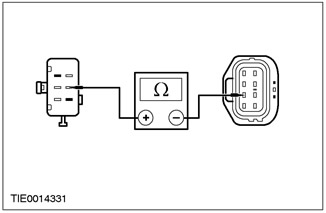
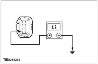
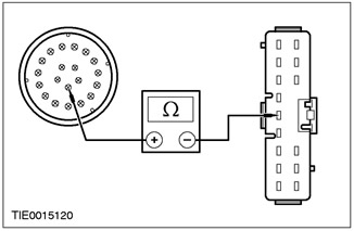
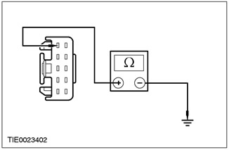
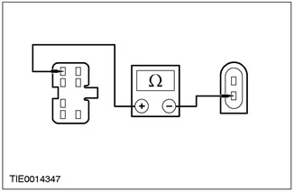
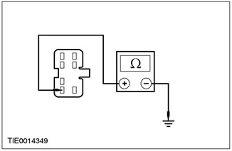
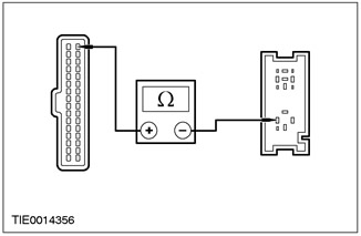
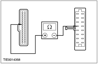
3 Measure the resistance between: NOTE: Passenger front power window - pin 5 C485 of the front passenger window inoperative window switch, circuit 31S-AJ55B (black/red), wiring side, and pin 3 C735 of the power window regulator motor, circuit 31S-AJ55A (black/red), from the side of the electrical wiring. NOTE: Left rear passenger power window - pin 5 C482 left rear passenger door inoperative window switch, circuit 31S-AJ46B (black/white), wiring side, and pin 3 C736 of the power window regulator motor, circuit 31S-AJ46A (black/white), from the side of the electrical wiring. NOTE:Right rear passenger power window - pin 5 C483 right rear passenger door inoperative power window switch circuit 31S-AJ46B (black/white), wiring side, and pin 3 C737 of the power window regulator motor, circuit 31S-AJ46A (black/white), from the side of the electrical wiring. |
|
• Is the resistance less than 5 ohms? |
|
|
→ Yes |
|
|
Go to J4. |
|
|
→ No |
|
|
REPAIR circuit 31S-AJ55B (black/red); or electrical circuit 31S-AJ46B (black/white). CHECK the system is working properly. |
|
|
J4: INSPECT FOR OPEN BETWEEN POWER WINDOW SWITCH ISN'T WORKING AND MOTOR DOWN CIRCUIT |
|
|
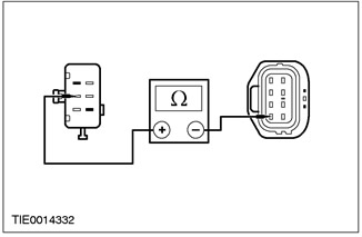
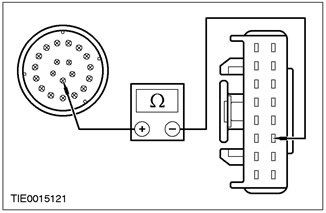
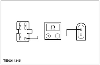
1 Measure the resistance between: NOTE: Passenger front power window - pin 2 C485 front passenger window inoperative window switch, circuit 31S-AJ54B (black/green), wiring side, and pin 4 C735 of the power window regulator motor, circuit 31S-AJ54A (black/green), from the side of the electrical wiring. NOTE: Left rear passenger power window - pin 2 C482 left rear passenger door inoperative power window switch circuit 31S-AJ63B (black/green), wiring side, and 4C736 power window regulator motor pin, circuit 31S-AJ63A (black/blue), from the side of the electrical wiring. NOTE:Right rear passenger power window - pin 2 C483 right rear passenger door inoperative power window switch circuit 31S-AJ63B (black/blue), wiring side, and pin 4 C737 of the power window regulator motor, circuit 31S-AJ63A (black/blue), from the side of the electrical wiring. |
|
• Is the resistance less than 5 ohms? |
|
|
→ Yes |
|
|
Go to J5. |
|
|
→ No |
|
|
REPAIR circuit 31S-AJ54B (black/green); or electrical circuit 31S-AJ63B (black/green); or electrical circuit 31S-AJ63B (black/blue). CHECK the system is working properly. |
|
|
J5: INSPECT POWER WINDOW REGULATOR MOTOR GROUND CIRCUIT OUT OF WORK |
|
|
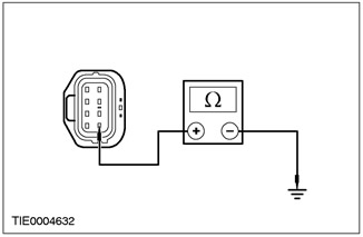
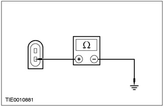
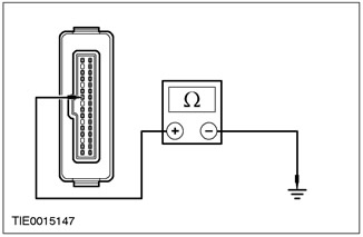
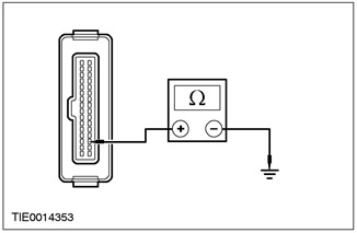
1 Measure the resistance between: NOTE:Driver's window with power window - pin 8 C734 driver's window idle power window regulator motor, circuit 31-AJ26 (black), from the wiring side, and "weight". NOTE: Passenger front power window - pin 8 C735 of the electric motor of the regulator of an inoperative front passenger window, circuit 31-AJ27 (black), from the wiring side, and "weight". NOTE: Left rear passenger power window - pin 8 C736 of the inoperative power window regulator motor, left rear passenger window, circuit 31-AJ31 (black), from the wiring side, and "weight". NOTE:Right rear passenger power window - pin 8 C737 of the right rear passenger window inoperative window regulator motor, circuit 31-AJ31 (black), from the wiring side, and "weight". |
|
• Is the resistance less than 5 ohms? |
|
|
→ Yes |
|
|
Check the validity of the customer's complaint. |
|
|
→ No |
|
|
REPAIR circuit 31-AJ26 (black); or electrical circuit 31-AJ27 (black); or electrical circuit 31-AJ31 (black). CHECK the system is working properly. |
|
|
J6: CHECK THE VOLTAGE AT THE POWER WINDOW SWITCH ISN'T WORKING |
|
|
1 Enter the OFF position. |
|
|
2 Disconnect the Power Window Inoperative Switch. |
|
|
3 Drive the ON position. |
|
|
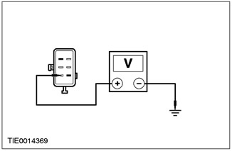
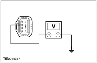
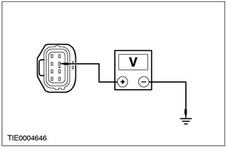
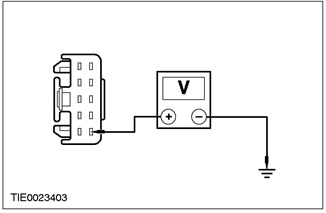
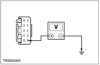
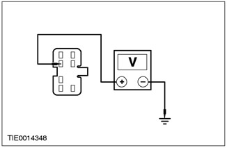
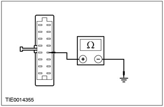
4 Measure the voltage between: NOTE: Passenger window power window switch shown. NOTE:Driver's window with power window - pin 13 C484 driver's window inoperative power window switch, circuit 15-LH14 (green/yellow), from the wiring side, and "weight". NOTE: Passenger front power window - pin 1 C485 of the front passenger window inoperative window switch, circuit 15-LH31 (green/blue), from the wiring side, and "weight". NOTE: Left rear passenger power window - pin 1 C482 left rear passenger door inoperative power window switch circuit 15-LH36 (green/red), from the wiring side, and "weight". NOTE:Right rear passenger power window - pin 1 C483 right rear passenger door inoperative power window switch circuit 15-LH36 (green/red), from the wiring side, and "weight". |
|
• Is the voltage over 10 V? |
|
|
→ Yes |
|
|
Go to J7. |
|
|
→ No |
|
|
Go to J14. |
|
|
J7: INSPECT POWER WINDOW SWITCH GROUND CIRCUIT INTO WORK |
|
|
1 Enter the OFF position. |
|
|
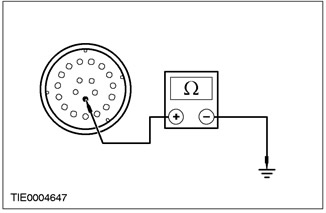
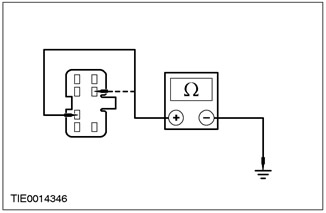
2 Measure the resistance between: NOTE: Driver's window power window switch shown. NOTE:Driver's window with power window - pin 4 C484 of the driver's door window inoperative power window switch, circuit 31-AJ7 (black), from the wiring side, and "weight". NOTE: Passenger front power window - pin 6 C485 of the front passenger window inoperative window switch, circuit 31-AJ18 (black), from the wiring side, and "weight". NOTE: Left rear passenger power window - pin 6 C482 of the left rear passenger door inoperative window switch, circuit 31S-AJ32 (black/orange), from the wiring side, and "weight". NOTE:Right rear passenger power window - pin 6 C483 of the right rear passenger door inoperative window switch, circuit 31S-AJ32 (black/orange), from the wiring side, and "weight". |
|
• Is the resistance less than 5 ohms? |
|
|
→ Yes |
|
|
Check the validity of the customer's complaint. |
|
|
→ No |
|
|
REPAIR circuit 31-AJ7 (black); or electrical circuit 31-AJ18 (black); or electrical circuit 31S-AJ32 (black/orange) or 31S-AJ14 (black/orange); or electrical circuit 31S-AJ32 (black/orange) or 31S-AJ24 (black/yellow). CHECK the system is working properly. |
|
|
J8: CHECK THE VOLTAGE SUPPLIED TO THE DOOR CONNECTOR WITH THE POWER WINDOW NOT WORKING |
|
|
1 Enter the OFF position. |
|
|
2 Disconnect the Power Window Door Connector. |
|
|
3 Drive the ON position. |
|
|
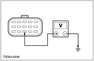
4 Measure the voltage between: NOTE:Driver's window with power window - pin 9 C42 driver's door with inoperative power window, electrical circuit 29-AJ26 (orange/yellow), from the wiring side, and "weight". NOTE: Passenger front power window - pin 9 C44 front passenger door with inoperative power window, electrical circuit 29-AJ27 (orange/white), from the wiring side, and "weight". NOTE: Left rear passenger power window - pin 9 C45 left rear passenger door with inoperative power window, circuit 29-AJ13 (orange/blue), from the wiring side, and "weight". NOTE:Right rear passenger power window - pin 9 C46 right rear passenger door with inoperative power window, electrical circuit 29-AJ23 (orange/white), from the wiring side, and "weight". |
|
• Is the voltage over 10 V? |
|
|
→ Yes |
|
|
Go to J9. |
|
|
→ No |
|
|
REPAIR circuit 29-AJ26 (orange/yellow); or electrical circuit 29-AJ27 (orange/white); or electrical circuit 29-AJ13 (orange/blue); or electrical circuit 29-AJ23 (orange/white). CHECK the system is working properly. |
|
|
J9: INSPECT POWER WINDOW REGULATOR MOTOR GROUND CIRCUIT OUT OF WORK |
|
|
1 Enter the OFF position. |
|
|
2 Disconnect the idle power window regulator motor. |
|

|
3 Measure the resistance between: NOTE:Driver's window with power window - pin 8 C734 driver's window idle power window regulator motor, circuit 31-AJ26 (black), from the wiring side, and "weight". NOTE: Passenger front power window - pin 8 C735 of the electric motor of the regulator of an inoperative front passenger window, circuit 31-AJ27 (black), from the wiring side, and "weight". NOTE: Left rear passenger power window - pin 8 C736 of the inoperative power window regulator motor, left rear passenger window, circuit 31-AJ31 (black), from the wiring side, and "weight". NOTE:Right rear passenger power window - pin 8 C737 of the right rear passenger window inoperative window regulator motor, circuit 31-AJ31 (black), from the wiring side, and "weight". |
|
• Is the resistance less than 5 ohms? |
|
|
→ Yes |
|
|
Go to J10. |
|
|
→ No |
|
|
REPAIR circuit 31-AJ26 (black); or electrical circuit 31-AJ27 (black); or electrical circuit 31-AJ31 (black). CHECK the system is working properly. |
|
|
J10: CHECK THE VOLTAGE SUPPLIED TO THE POWER WINDOW ADJUSTER MOTOR CONNECTOR OFF |
|
|
1 Connect the door connector with the power window not working. |
|
|
2 Drive the ON position. |
|
|
3 Measure the voltage between: NOTE:Driver's window with power window - pin 7 C734 driver's window idle power window regulator motor, circuit 29-AJ26 (orange/yellow), from the wiring side, and "weight". NOTE: Passenger front power window - pin 7 C735 of the electric motor of the regulator of an inoperative front passenger window, circuit 29-AJ27 (orange/white), from the wiring side, and "weight". NOTE: Left rear passenger power window - pin 7 C736 of the electric motor of the regulator of the inoperative power window of the left rear passenger window, circuit 29-AJ31 (orange/blue), from the wiring side, and "weight". NOTE:Right rear passenger power window - pin 7 C737 of the right rear passenger window inoperative window regulator motor, circuit 29-AJ31 (orange/blue), from the wiring side, and "weight". |
|
• Is the voltage over 10 V? |
|
|
→ Yes |
|
|
Go to J11. |
|
|
→ No |
|
|
REPAIR circuit 29-AJ26 (orange/yellow); or electrical circuit 29-AJ27 (orange/white); or electrical circuit 29-AJ31 (orange/blue). CHECK the system is working properly. |
|
|
J11: INSPECT FOR OPEN IN POWER WINDOW CONTROL MOTOR LIFTING CIRCUIT IN INDEPENDENT |
|
|
1 Enter the OFF position. |
|
|
2 Press the power window regulator motor switch in the UP position. |
|
|
3 Measure the resistance between: NOTE:Driver's window with power window - pin 3 C734 driver's window inoperative window regulator motor, circuit 31S-AJ41 (black/red) LHD ([black/orange] RHD), from the wiring side, and "weight". NOTE: Passenger front power window - pin 3 C735 of the electric motor of the regulator of an inoperative front passenger window, circuit 31S-AJ55A (black/red), from the wiring side, and "weight". NOTE: Left rear passenger power window - pin 3 C736 of the electric motor of the regulator of an inoperative power window of the left rear passenger window, circuit 31S-AJ46A (black/white), from the wiring side, and "weight". NOTE:Right rear passenger power window - pin 3 C737 of the right rear passenger window inoperative window regulator motor, circuit 31S-AJ46A (black/white), from the wiring side, and "weight". |
|
• Is the resistance less than 5 ohms? |
|
|
→ Yes |
|
|
Go to J12 |
|
|
→ No |
|
|
REPAIR circuit 31S-AJ41 (black/red) LHD ([black/orange] RHD); or electrical circuit 31S-AJ55A (black/red) or 31S-AJ55B (black/red); or electrical circuit 31S-AJ46A (black/red); or electrical circuit 31S-AJ46A (black/white) or 31S-AJ46B (black/white). CHECK the system is working properly. |
|
|
J12: INSPECT FOR OPEN IN POWER WINDOW CONTROL MOTOR DOWN CIRCUIT |
|
|
1 Press the inoperative power window regulator motor switch to the DOWN position. |
|
|
2 Measure the resistance between: NOTE:Driver's window with power window - pin 4 C734 driver's window idle power window regulator motor, circuit 31S-AJ40 (black/green) LHD ([black/blue] RHD), from the wiring side, and "weight". NOTE: Passenger front power window - pin 4 C735 of the electric motor of the regulator of an inoperative front passenger window, circuit 31S-AJ54A (black/green), from the wiring side, and "weight". NOTE: Left rear passenger power window - pin 4 C736 inoperative power window regulator motor, left rear passenger window, circuit 31S-AJ63A (black/blue), from the wiring side, and "weight". NOTE:Right rear passenger power window - pin 4 C737 of the right rear passenger window inoperative window regulator motor, circuit 31S-AJ63A (black/blue), from the wiring side, and "weight". |
|
• Is the resistance less than 5 ohms? |
|
|
→ Yes |
|
|
Go to J13. |
|
|
→ No |
|
|
REPAIR circuit 31S-AJ40 (black/green) LHD ([black/blue] RHD); or electrical circuit 31S-AJ54A (black/green) or 31S-AJ54B (black/green); or electrical circuit 31S-AJ63A (black/blue) or electrical circuit 31S-AJ63B (black/green). CHECK the system is working properly. |
|
|
J13: CHECK THE VOLTAGE SUPPLIED TO THE POWER WINDOW REGULATOR MOTOR OFF |
|
|
1 Measure the voltage between: NOTE:Driver's window with power window - pin 2 C734 driver's window inoperative window regulator motor, circuit 15-AJ26 (green/yellow), from the wiring side, and "weight". NOTE: Passenger front power window - pin 2 C735 of the electric motor of the regulator of an inoperative front passenger window, circuit 31S-AJ27A (green/white), from the wiring side, and "weight". NOTE: Left rear passenger power window - pin 2 C736 of the left rear passenger window inoperative window regulator motor, circuit 31S-AJ13A (green/blue), from the wiring side, and "weight". NOTE:Right rear passenger power window - pin 2 C737 of the right rear passenger window inoperative window regulator motor, circuit 31S-AJ31A (green/blue), from the wiring side, and "weight". |
|
• Is the voltage over 10 V? |
|
|
→ Yes |
|
|
INSTALL a new window regulator motor. For more information, refer to Window Regulator Motor available in this section. CHECK the system is working properly. |
|
|
→ No |
|
|
REPAIR circuit 15-AJ26A (green/yellow); or electrical circuit 31S-AJ27A (green/white) or 31S-AJ54B (black/green); or electrical circuit 31S-AJ31A (green/blue). CHECK the system is working properly. |
|
|
J14: CHECK THE VOLTAGE SUPPLIED TO THE DOOR CONNECTOR WITH THE POWER WINDOW NOT WORKING |
|
|
1 Disconnect the Power Window Door Connector. |
|
|
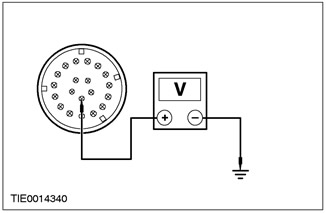
2 Measure the voltage between: NOTE: B-pillar connector shown. NOTE:Driver's window with power window - pin 15 C42 driver's door with inoperative power window, electrical circuit 15-AJ26 (green/yellow) LHD (circuit 15-AJ27 [green/white] RHD), from the A-pillar side, and "weight". NOTE: Passenger front power window - pin 15 C44 front passenger door with inoperative power window, electrical circuit 15-AJ27 (green/white) LHD (circuit 15-AJ26 [green/yellow] RHD), from the A-pillar side, and "weight". NOTE: Left rear passenger power window - pin 13 C45 left rear passenger door with inoperative power window, electrical circuit 15-AJ13 (green/blue), on the B-pillar side, and "weight". NOTE:Right rear passenger power window - pin 13 C46 right rear passenger door with inoperative power window, electrical circuit 15-AJ13 (green/blue), on the B-pillar side, and "weight". |
|
• Is the voltage over 10 V? |
|
|
→ Yes |
|
|
REPAIR circuit 15-AJ26 (green/yellow) door side or electrical circuit 15-LH14 (green/yellow); or electrical circuit 15-AJ27 (green/white) or electrical circuit 15-LH31 (green/blue); or electrical circuit 15-AJ31 (green/blue) or 15-LH36 (green/red). CHECK the system is working properly. |
|
|
→ No |
|
|
REPAIR circuit 15-AJ26 (green/yellow) from the A-pillar; or electrical circuit 15-AJ27 (green/white); or electrical circuit 15-AJ13 (green/blue). CHECK the system is working properly. |
|
PINPOINT TEST K: GENERAL CLOSE FUNCTION DOES NOT WORK
|
STATES |
DETAILS/RESULTS/ACTIONS |
|
NOTE: Make sure all power window motors are initialized. |
|
|
K1: CHECK CENTRAL TIMER MODULE - CONNECTION TO CENTRAL SECURITY MODULE |
|
|
1 Check the lock button on the remote control. |
|
|
• Do the interior lights turn off? |
|
|
→ Yes |
|
|
Go to K2. |
|
|
→ No |
|
|
REPAIR the electrical circuit (And). See Section 419-10 for more information. |
|
|
K2: CHECK THE VOLTAGE SUPPLIED TO THE DOOR WINDOW ISN'T WORKING CONNECTOR |
|
|
1 Disconnect the Power Window Door Connector. |
|
|
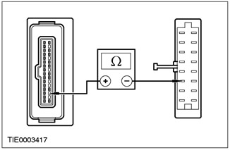
2 Measure the voltage between: NOTE: A-pillar connector shown. NOTE:Driver's window with power window - pin 16 C42 driver's door with inoperative power window, electrical circuit 8-AJ42 (white/green), from the A-pillar side, and "weight". NOTE: Passenger front power window - pin 16 C44 front passenger door with inoperative power window, electrical circuit 8-AJ56 (white/green), from the A-pillar side, and "weight". NOTE: Left rear passenger power window - pin 11 C45 left rear passenger door with inoperative power window, electrical circuit 8-AJ59 (white/green), on the B-pillar side, and "weight". NOTE:Right rear passenger power window - pin 11 C46 right rear passenger door with inoperative power window, electrical circuit 8-AJ62 (white/green), on the B-pillar side, and "weight". |
|
• Is the voltage over 10 V? |
|
|
→ Yes |
|
|
Go to K3. |
|
|
→ No |
|
|
Go to K4. |
|
|
K3: CHECK THE VOLTAGE SUPPLIED TO THE POWER WINDOW REGULATOR MOTOR OFF |
|
|
1 Connect the door connector with the power window not working. |
|
|
2 Disconnect the Inoperative Power Window Regulator Motor Connector. |
|
|
3 Measure the voltage between: NOTE:Driver's window with power window - pin 6 C734 driver's window inoperative power window regulator motor, circuit 8-AJ42 (white/green), from the wiring side, and "weight". NOTE: Passenger front power window - pin 6 C735 passenger window inoperative power window regulator motor, circuit 8-AJ56 (white/green), from the wiring side, and "weight". NOTE: Left rear passenger power window - pin 6 C737 of the electric motor of the regulator of the inoperative power window of the left rear passenger window, circuit 8-AJ65 (white/green), from the wiring side, and "weight". NOTE:Right rear passenger power window - pin 6 C736 of the right rear passenger window inoperative window regulator motor, circuit 8-AJ65 (white/green), from the wiring side, and "weight". |
|
• Is the voltage over 10 V? |
|
|
→ Yes |
|
|
INSTALL a new window regulator motor. REFER to the procedure in this section: Window regulator motor. CHECK the system is working properly. |
|
|
→ No |
|
|
REPAIR circuit 8-AJ42 (white/green); or 8-AJ56 (white/green) or 8-AJ65 (white/green). CHECK the system is working properly. |
|
|
K4: CHECK FLOOR WIRING FOR SHORT CIRCUIT WITH "MASS" |
|
|
NOTE: Circuit numbers change at connection point S152. |
|
|
1 Disconnect All door connectors. |
|
|
2 Disconnect the Central Timer Module - C1000. |
|
|
3 Measure the resistance between pin 16 C42 of the driver's door connector, circuit 8-AJ42 (white/green), from the A-pillar side, and "weight". |
|
• Is the resistance over 10,000 ohms? |
|
|
→ Yes |
|
|
Go to K5. |
|
|
→ No |
|
|
REPAIR floor circuit wiring 8-AJ42 (white/green); or 8-AJ56 (white/green); or 8-AJ59 (white/green); or 8-AJ65 (white/green). CHECK the system is working properly. |
|
|
K5: CHECK FOR OPEN BETWEEN POWER WINDOW DRIVER'S DOOR CONNECTOR AND CENTRAL CONNECTION BOX |
|
|
1 Disconnect the central junction box - C15. |
|
|
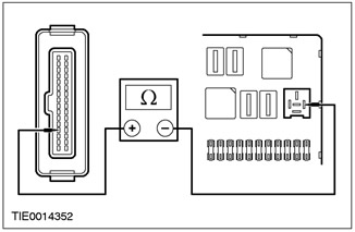
2 Measure the resistance between pin 16 C42 of the driver's door connector, circuit 8-AJ42 (white/green), on the A-pillar side, and pin 11 C15 of the central connection box, circuit 8-AA36 (white), from the side of the electrical wiring. |
|
• INSTALL a new relay. |
|
|
→ Yes |
|
|
Go to K6. |
|
|
→ No |
|
|
REPAIR circuit 8-AA36 or 8-AA36A (white). REPAIR chain 32-AJ26 (white). |
|
|
K6: CHECK FOR OPEN BETWEEN DRIVER'S POWER WINDOW DOOR CONNECTOR AND CENTRAL SECURITY UNIT. |
|
|
1 Disconnect the Central Security Module - C451. |
|
|
2 Measure the resistance between pin 16 C42 of the driver's door connector, circuit 8-AJ42 (white/green), A-pillar side, and pin 14 C451, circuit 8-AA36 (white), from the side of the electrical wiring. |
|
• INSTALL a new switch. |
|
|
→ Yes |
|
|
REPAIR chain 32-AJ26 (white). |
|
|
→ No |
|
|
REPAIR circuit 8-AA36 (white). Check the switching voltage applied to the open/close relay "one touch" |
|
PINPOINT TEST L: ALL POWER WINDOWS DO NOT WORK - FRONT POWER WINDOWS
|
STATES |
DETAILS/RESULTS/ACTIONS |
|
L1: CHECK THE VOLTAGE SUPPLIED TO THE POWER WINDOW SWITCHES |
|
|
1 Drive the ON position. |
|
|
• Are the power window switch LEDs lit? |
|
|
→ Yes |
|
|
CHECK the legitimacy of the customer's complaint. |
|
|
→ No |
|
|
Go to L2. |
|
|
L2: INSPECT FOR OPEN BETWEEN DRIVER'S DOOR WINDOW SWITCH AND "MASS" |
|
|
1 Enter the OFF position. |
|
|
2 Disconnect Driver's Window Power Window Switch - C488. |
|
|
3 Measure the resistance between C488 pin 1 of the driver's window power window switch, circuit 31-AJ7 (black), from the wiring side, and "weight". |
|
• Is the resistance less than 5 ohms? |
|
|
→ Yes |
|
|
Go to L3. |
|
|
→ No |
|
|
REPAIR circuit 31-AJ7 (black). Check the correct operation of the system. |
|
|
L3: CHECK VOLTAGE AT DRIVER'S DOOR WINDOW SWITCH |
|
|
1 Drive the ON position. |
|
|
2 Measure the voltage between pin 10 of C488 driver's window power window switch, circuit 15-AJ7 (green/blue), from the wiring side, and "weight". |
|
• Is the voltage over 10 V? |
|
|
→ Yes |
|
|
Check the validity of the customer's complaint. |
|
|
→ No |
|
|
REPAIR circuit 15-AJ7 (green/brown). Check the correct operation of the system. |
|
PINPOINT TEST M: ONE WINDOW WITH ELECTRIC WINDOW DOES NOT WORK - DRIVER SIDE
|
STATES |
DETAILS/RESULTS/ACTIONS |
|
M1: CHECK VOLTAGE AT DRIVER'S DOOR WINDOW SWITCH |
|
|
1 Drive the ON position. |
|
|
• Is the driver's door power window switch LED on? |
|
|
→ Yes |
|
|
Go to M2. |
|
|
→ No |
|
|
Go to M4. |
|
|
M2: CHECK FOR OPEN BETWEEN DRIVER'S DOOR WINDOW CONTROL MOTOR AND "MASS" |
|
|
1 Enter the OFF position. |
|
|
2 Disconnect the Driver's Window Regulator Motor - C782. |
|
|
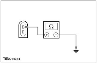
3 Measure the resistance between C782 pin 1 of the driver's window regulator motor, circuit 33-AJ26 (yellow), from the wiring side, and "weight". |
|
• Is the resistance less than 5 ohms? |
|
|
→ Yes |
|
|
Go to M3. |
|
|
→ No |
|
|
CHECK the system is working properly. Check for open circuit between open/close relay "one touch" and driver window power window switch |
|
|
M3: CHECK SWITCH VOLTAGE SUPPLIED TO DRIVER'S DOOR WINDOW CONTROL MOTOR |
|
|
1 Drive the ON position. |
|
|
2 Push the driver's window power window switch to the DOWN position. |
|
|
3 Measure the voltage between C782 pin 2 of the driver's door window regulator motor, circuit 32-AJ26 (white), from the wiring side, and "weight". |
|
• REPAIR chain 32-AJ17 (white/purple). |
|
|
→ Yes |
|
|
INSTALL a new driver's window regulator motor. For more information, refer to Window Regulator Motor available in this section. CHECK the system is working properly. |
|
|
→ No |
|
|
CHECK the system is working properly. Perform a driver window power window switch component test. |
|
|
M4: INSPECT FOR OPEN BETWEEN DRIVER'S DOOR WINDOW SWITCH AND "MASS" |
|
|
1 Enter the OFF position. |
|
|
2 Disconnect Driver's Window Power Window Switch - C488. |
|

|
3 Measure the resistance between C488 pin 1 of the driver's window power window switch, circuit 31-AJ7 (black), And "weight". |
|
• Is the resistance less than 5 ohms? |
|
|
→ Yes |
|
|
Go to M5. |
|
|
→ No |
|
|
REPAIR circuit 31-AJ7 (black). CHECK the system is working properly. |
|
|
M5: CHECK VOLTAGE SUPPLIED TO DRIVER'S DOOR WINDOW SWITCH |
|
|
1 Push the driver's window power window switch to the UP position. |
|
|
2 Measure the voltage between pin 10 of C488 driver's window power window switch, circuit 15-AJ7 (green/blue), And "weight". |
|
• Is the voltage over 10 V? |
|
|
→ Yes |
|
|
Check the validity of the customer's complaint. |
|
|
→ No |
|
|
REPAIR circuit 15-AJ7 (green/brown). CHECK the system is working properly. |
|
PINPOINT TEST N: ONE WINDOW WITH ELECTRIC WINDOW DOES NOT WORK - PASSENGER SIDE
|
STATES |
DETAILS/RESULTS/ACTIONS |
|
N1: CHECK VOLTAGE AT PASSENGER DOOR WINDOW SWITCH |
|
|
1 Drive the ON position. |
|
|
• Is the passenger's door power window switch LED on? |
|
|
→ Yes |
|
|
Go to N2. |
|
|
→ No |
|
|
Go to N5. |
|
|
N2: INSPECT PASSENGER DOOR WINDOW SWITCH GROUND CIRCUITS |
|
|
1 Enter the OFF position. |
|
|
2 Disconnect Passenger Window Power Window Switch - C489. |
|
|
3 Measure the resistance between pin 3 of C489 passenger window power window switch, circuit 32-AJ18 (white/purple), from the wiring side, and "weight"; and between pin 6 C489 passenger window power window switch circuit 33-AJ18 (yellow/purple), from the wiring side, and "weight". |
|
• Is the resistance less than 5 ohms in all cases? |
|
|
→ Yes |
|
|
Go to N3. |
|
|
→ No |
|
|
Repair circuit 32-AJ18 (white/purple) or electrical circuit 33-AJ18 (yellow/purple). CHECK the system is working properly. |
|
|
N3: INSPECT FOR OPEN BETWEEN PASSENGER DOOR WINDOW SWITCH AND PASSENGER DOOR WINDOW CONTROL MOTOR |
|
|
1 Disconnect the Passenger Window Regulator Motor - C783. |
|
|
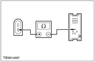
2 Measure the resistance between C489 pin 1 of the passenger window power window switch, circuit 33-AJ17 (yellow/purple), wiring side, and pin 1 C783 passenger window regulator motor, circuit 33-AJ17 (yellow/purple), from the side of the electrical wiring. |
|
• Is the resistance less than 5 ohms? |
|
|
→ Yes |
|
|
Go to N4. |
|
|
→ No |
|
|
CHECK the system is working properly. opening function "one touch" does not work |
|
|
N4: INSPECT FOR OPEN BETWEEN PASSENGER DOOR WINDOW SWITCH AND PASSENGER DOOR WINDOW CONTROL MOTOR |
|
|
1 Measure the resistance between pin 7 of C489 passenger window power window switch circuit 32-AJ17 (white/purple), wiring side, and pin 2 C783 passenger window regulator motor, circuit 32-AJ17 (white/purple), from the side of the electrical wiring. |
|
• Check the legitimacy of the customer's complaint. |
|
|
→ Yes |
|
|
INSTALL a new window regulator motor. For more information, refer to Window Regulator Motor available in this section. CHECK the system is working properly. |
|
|
→ No |
|
|
CHECK the system is working properly. Check the voltage supplied to the passenger window motor close circuit |
|
|
N5: INSPECT PASSENGER DOOR WINDOW SWITCH GROUND CIRCUIT |
|
|
1 Enter the OFF position. |
|
|
2 Disconnect Passenger Window Power Window Switch - C489. |
|
|
3 Measure the resistance between pin 4 of C489 passenger window power window switch circuit 31-LH31 (black), from the wiring side, and "weight". |
|
• Is the resistance less than 5 ohms? |
|
|
→ Yes |
|
|
Go to N6. |
|
|
→ No |
|
|
REPAIR chain 31-LH31 (black). CHECK the system is working properly. |
|
|
N6: CHECK VOLTAGE AT PASSENGER DOOR WINDOW SWITCH |
|
|
1 Drive the ON position. |
|
|
2 Measure the voltage between pin 2 of C489 passenger window power window switch circuit 15-AJ18 (green/white), from the wiring side, and "weight". |
|
• Is the voltage over 10 V? |
|
|
→ Yes |
|
|
Check the validity of the customer's complaint. |
|
|
→ No |
|
|
REPAIR circuit 15-AJ18 (green/white). CHECK the system is working properly. |
|
PINPOINT TEST O: DEICING SYSTEM DOES NOT WORK
|
STATES |
DETAILS/RESULTS/ACTIONS |
|
O1: INSPECT REAR WINDOW HEATED ELECTRIC CIRCUIT |
|
|
1 Drive the ON position. |
|
|
2 Press the heated rear window switch. |
|
|
• Is the heated rear window electrical circuit functioning correctly? |
|
|
→ Yes |
|
|
Go to O2. |
|
|
→ No |
|
|
Go to O3. |
|
|
O2: INSPECT HEATED WINDSHIELD ELECTRICAL CIRCUIT |
|
|
1 Drive the START position. |
|
|
2 Drive the ON position. |
|
|
3 With the engine running, press the heated windshield switch. |
|
|
• Is the heated windshield electrical circuit functioning correctly? |
|
|
→ Yes |
|
|
Check the validity of the customer's complaint. |
|
|
→ No |
|
|
Go to O6. |
|
|
O3: CHECK OPERATION OF HEATED EXTERIOR MIRRORS |
|
|
1 Press the heated rear window switch. |
|
|
• Does the exterior mirror heating function correctly? |
|
|
→ Yes |
|
|
Go to O4. |
|
|
→ No |
|
|
Go to O10. |
|
|
O4: CHECK THE VOLTAGE SUPPLIED TO THE REAR WINDOW GRILLE WIRE |
|
|
1 Enter the OFF position. |
|
|
2 Disconnect the heated rear window grille wire. |
|
|
3 Drive the ON position. |
|
|
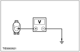
4 Measure the voltage between: NOTE: All models before 08/1999 - pin 1 C951 heated rear window grille, electrical circuit 15S-HB19 (green/blue), from the wiring side, and "weight". NOTE: 3-door variant, 5-door variant and "station wagon", issued since 09/1999 - pin 1 C949 heated rear window grille, electrical circuit 15S-HB19 (green/blue), from the wiring side, and "weight". NOTE: 4-door variant since 01/2000 - pin 1 C950 heated rear window grille, electrical circuit 15S-HB19 (green/blue), from the wiring side, and "weight". |
|
• Is the voltage over 10 V? |
|
|
→ Yes |
|
|
3-door and 5-door, INSTALL a new heated rear window. CHECK the system is working properly. 4-door variant and "station wagon", Go to O5. |
|
|
→ No |
|
|
REPAIR circuit 15S-HB19 (green/blue). CHECK the system is working properly. |
|
|
O5: INSPECT GRILLE GRILLE GROUND GROUND CIRCUIT |
|
|
1 Enter the OFF position |
|

|
2 Measure the resistance between: NOTE: "station wagon", released before 08/1999 - pin 1 C950 heated rear window grille, electrical circuit 31-HB19 (black), from the wiring side, and "weight". NOTE: "station wagon", issued since 09/1999 - pin 1 C948 heated rear window grille, circuit 31-HB19 (black), from the wiring side, and "weight". NOTE: 4-door version before 12/1999 - pin 1 C950 heated rear window grille, electrical circuit 31-HB19 (black), from the wiring side, and "weight". NOTE: 4-door version since 01/2000 - pin 1 C951 heated rear window grille, circuit 31-HB19 (black), from the wiring side, and "weight". |
|
• INSTALL a new switch. |
|
|
→ Yes |
|
|
INSTALL a new heated rear window. CHECK the system is working properly. |
|
|
→ No |
|
|
REPAIR Circuit 31-HB35 (black). CHECK the system is working properly. |
|
|
O6: INSPECT HEATED WINDSHIELD RELAY |
|
|
1 With the engine running, press the heated windshield switch. |
|
|
• Does the relay click with a distinct click? |
|
|
→ Yes |
|
|
Go to O7. |
|
|
→ No |
|
|
Go to O14. |
|
|
O7: CHECK THE VOLTAGE SUPPLIED TO THE WIRES OF THE HEATED WINDSHIELD GRILLE |
|
|
1 Enter the OFF position. |
|
|
2 Disconnect the Heated Windshield Grille Wire. |
|
|
3 Drive the START position. |
|
|
4 Drive the ON position. |
|
|
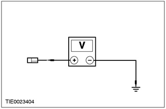
5 Measure the voltage between: NOTE: Left grille wire - pin 1 C634 left wire of heated windscreen grille, electrical circuit 64S-HB12 (brown), from the wiring side, and "weight". NOTE: Right grille wire - pin 1 C635 of the right wire of the heated windshield grille, electrical circuit 64S-HB25 (brown/red), from the wiring side, and "weight". |
|
• Is the voltage more than 10 V in all cases? |
|
|
→ Yes |
|
|
Go to O8. |
|
|
→ No |
|
|
Go to O17. |
|
|
O8: INSPECT GROUND WIRES OF HEATED WINDSHIELD WIRE |
|
|
1 Enter the OFF position. |
|
|
2 Measure the resistance between the heated windshield and "weight". |
|
|
• Is the resistance less than 5 ohms in all cases? |
|
|
→ Yes |
|
|
Go to O9. |
|
|
→ No |
|
|
REPAIR the heated windshield ground circuit. CHECK the system is working properly. |
|
|
O9: CHECK HEATED WINDSHIELD GRILLS |
|
|
1 Measure the resistance between: NOTE: Left grille wire - pin 1 C634 of the heated windshield grille wire, on the element side, and "weight". NOTE: Right grille wire - pin 1 C635 of the heated windshield grille wire, on the element side, and "weight". |
|
• Is the resistance over 10,000 ohms? |
|
|
→ Yes |
|
|
INSTALL a new windshield. CHECK the system is working properly. |
|
|
→ No |
|
|
Check the validity of the customer's complaint. |
|
|
O10: PRESS THE HEATED REAR WINDOW SWITCH. |
|
|
1 Press the heated rear window switch. |
|
|
• Check fuse F7 (40 A) |
|
|
→ Yes |
|
|
Go to O11. |
|
|
→ No |
|
|
Go to O18. |
|
|
O11: CHECK THE VOLTAGE SUPPLIED TO THE FUSE 49 (25 A) CENTRAL CONNECTION BOX (CJB) |
|
|
1 Enter the OFF position. |
|
|
2 Disconnect Fuse 49 (25 A). |
|
|
3 Drive the ON position. |
|
|
4 Measure voltage between fuse input 49 (25 A) And "weight". |
|
• Is the voltage over 10 V? |
|
|
→ Yes |
|
|
Go to O12. |
|
|
→ No |
|
|
REPAIR the central junction box. CHECK the system is working properly. |
|
|
O12: CHECK THE VOLTAGE SUPPLIED TO THE REAR WINDOW GRILLE WIRE |
|
|
1 Enter the OFF position. |
|
|
2 Disconnect the Heated Rear Window Grill Wire.. |
|
|
3 Drive the ON position. |
|
|
4 Measure the voltage between: NOTE: All models before 08/1999 - pin 1 C951 heated rear window grille, electrical circuit 15S-HB19 (green/blue), from the wiring side, and "weight". NOTE: 3-door variant, 5-door variant and "station wagon", issued since 09/1999 - pin 1 C949 heated rear window grille, electrical circuit 15S-HB19 (green/blue), from the wiring side, and "weight". NOTE: 4-door version since 01/2000 - pin 1 C950 heated rear window grille, electrical circuit 15S-HB19 (green/blue), from the wiring side, and "weight". |
|
|
• Is the voltage over 10 V? |
|
|
→ Yes |
|
|
3-Door and 5-Door: INSTALL a new heated rear window. CHECK the system is working properly. 4-door variant and "station wagon", Go to O13. |
|
|
→ No |
|
|
REPAIR chain 15S-HB19 (green/blue). CHECK the system is working properly. |
|
|
O13: INSPECT GRILLE GRILLE GROUND GROUND |
|
|
1 Enter the OFF position. |
|
|
2 Disconnect the heated rear window grille. |
|
|
3 Measure the resistance between: NOTE: All models before 08/1999 - pin 1 C950 heated rear window grille, electrical circuit 31-HB19 (black), from the wiring side, and "weight". NOTE: "station wagon", issued since 09/1999 - pin 1 C948 heated rear window grille, circuit 31-HB19 (black), from the wiring side, and "weight". NOTE: 4-door version since 01/2000 - pin 1 C951 heated rear window grille, circuit 31-HB19 (black), from the wiring side, and "weight". |
|
• Is the resistance less than 5 ohms? |
|
|
→ Yes |
|
|
INSTALL a new heated rear window. CHECK the system is working properly. |
|
|
→ No |
|
|
REPAIR chain 31-HB19 (black). CHECK the system is working properly. |
|
|
O14: CHECK THE VOLTAGE SUPPLIED TO THE HEATED WINDSHIELD RELAY |
|
|
1 Enter the OFF position. |
|
|
2 Disconnect Heated Windshield Relay - C1003. |
|
|
3 Drive the START position. |
|
|
4 Drive the ON position. |
|
|
5 Measure voltage between pin 1 C1003 Heated windshield relay circuit 64-HB7 (brown/red), from the wiring side, and "weight". |
|
• Is the voltage over 10 V? |
|
|
→ Yes |
|
|
Go to O15. |
|
|
→ No |
|
|
REPAIR Circuit 64-HB7 (brown/red). CHECK the system is working properly. |
|
|
O15: CHECK FOR OPEN BETWEEN CENTRAL TIMER MODULE AND "MASS" |
|
|
1 Enter the OFF position. |
|
|
2 Press the heated windshield switch. |
|
|
3 Measure the resistance between C1000 pin 10 of the central timer module, wiring side, and "weight". |
|
• Is the resistance less than 5 ohms? |
|
|
→ Yes |
|
|
Go to O16. |
|
|
→ No |
|
|
Go to O20. |
|
|
O16: CHECK FOR OPEN BETWEEN HEATED WINDSHIELD RELAY AND CENTRAL TIMER MODULE |
|
|
1 Measure the resistance between pin 2 C1003 Heated Windshield Relay Circuit 31S-HB7 (black/blue), on the wiring side, and pin 32 C1000 of the central timer module (CJB), from the side of the electrical wiring. |
|
• Is the resistance less than 5 ohms? |
|
|
→ Yes |
|
|
INSTALL a new heated windshield relay. CHECK the system is working properly. |
|
|
→ No |
|
|
REPAIR chain 31S-HB7 (black/blue). CHECK the system is working properly. |
|
|
O17: CHECK FOR OPEN BETWEEN HEATED WINDSHIELD RELAY AND HEATED WINDSHIELD GRILLE WIRES |
|
|
1 Enter the OFF position. |
|
|
2 Disconnect Heated Windshield Relay - C1003. |
|
|
3 Measure the resistance between: NOTE: Left grille wire - pin 5 C1003 heated windshield relay, electrical circuit 64S-HB1 (brown/red), from the wiring side, and pin 1 C634 of the left wire of the heated windshield grille, electrical circuit 64S-HB12 (brown), from the side of the electrical wiring. NOTE: Right grille wire - pin 5 C1003 heated windshield relay, electrical circuit 64S-HB1 (brown/red), from the wiring side, and pin 1 C635 of the right wire of the heated windshield grill, electrical circuit 64S-HB25 (brown/red), from the side of the electrical wiring. |
|
• Is the resistance less than 5 ohms in all cases? |
|
|
→ Yes |
|
|
INSTALL a new heated windshield relay. CHECK the system is working properly. |
|
|
→ No |
|
|
REPAIR circuit 64S-HB1 (brown/red), electrical circuit 64S-HB12 (brown) or electrical circuit 64S-HB25 (brown/red). CHECK the system is working properly. |
|
|
O18: CHECK FOR OPEN BETWEEN REAR WINDOW HEATED RELAY AND CENTRAL TIMER MODULE |
|
|
1 Enter the OFF position. |
|
|
2 Measure the resistance between pin 2 of the C1025 heated rear window relay (CJB), on the wiring side, and pin 4 C1000 of the central timer module (CJB), from the side of the electrical wiring. |
|
• Is the resistance less than 5 ohms? |
|
|
→ Yes |
|
|
Go to O19. |
|
|
→ No |
|
|
REPAIR the central junction box. Check the correct operation of the system. |
|
|
O19: CHECK FOR OPEN BETWEEN CENTRAL TIMER MODULE AND "MASS" |
|
|
1 Press the heated rear window switch. |
|
|
2 Measure the resistance between pin 19 C1000 of the central timer module (CJB), from the wiring side, and "weight". |
|
• Is the resistance less than 5 ohms? |
|
|
→ Yes |
|
|
INSTALL a new heated rear window relay. Check the correct operation of the system. |
|
|
→ No |
|
|
Go to O22. |
|
|
O20: CHECK FOR OPEN BETWEEN CENTRAL TIMER MODULE AND HEATER CONTROL MODULE |
|
|
1 Disconnect the heater control module - C380. |
|
|
2 Measure the resistance between C1000 pin 10 of the central timer module (CJB), on the wiring side, and pin 5 C380 of the heater control module, circuit 31S-HB9 (black/white), from the side of the electrical wiring. |
|
• Is the resistance less than 5 ohms? |
|
|
→ No |
|
|
Go to O21. |
|
|
→ No |
|
|
REPAIR circuit 31S-HB9 (black/white). Check the correct operation of the system. |
|
|
O21: INSPECT GROUND CIRCUIT OF HEATER CONTROL MODULE |
|
|
1 Measure the resistance between pin 12 C380 of the heater control module, circuit 91-FA13 (black/orange), from the wiring side, and "weight". |
|
• Is the resistance less than 5 ohms? |
|
|
→ Yes |
|
|
INSTALL a new heater control module. Check the correct operation of the system. |
|
|
→ No |
|
|
REPAIR circuit 91-FA13 (black/orange). Check the correct operation of the system. |
|
|
O22: CHECK FOR OPEN BETWEEN CENTRAL TIMER MODULE AND HEATER CONTROL MODULE |
|
|
1 Measure the resistance between pin 19 C1000 of the central timer module (CJB), on the wiring side, and pin 3 C380 of the heater control module, circuit 31S-HB1 (black/blue), from the side of the electrical wiring. |
|
• Is the resistance less than 5 ohms? |
|
|
→ Yes |
|
|
Go to O23. |
|
|
→ No |
|
|
REPAIR chain 31S-HB1 (black/blue). CHECK the system is working properly. |
|
|
O23: CHECK FOR OPEN BETWEEN HEATER CONTROL MODULE AND "MASS" |
|

|
1 Measure the resistance between pin 12 C380 of the heater control module, circuit 91-FA13 (black/orange), from the wiring side, and "weight". |
|
• Is the resistance less than 5 ohms? |
|
|
→ Yes |
|
|
INSTALL a new heater control module. CHECK the system is working properly. |
|
|
→ No |
|
|
REPAIR circuit 91-FA13 (black/orange). CHECK the system is working properly. |
|
Visitor comments