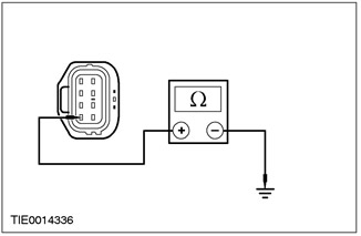
NOTE: Use a digital multimeter to make all electrical measurements.
PINPOINT TEST A: POWER WINDOWS INOPERATIVE ON ALL WINDOWS - POWER WINDOWS ON FRONT AND REAR DOORS
|
STATES |
DETAILS/RESULTS/ACTIONS |
|
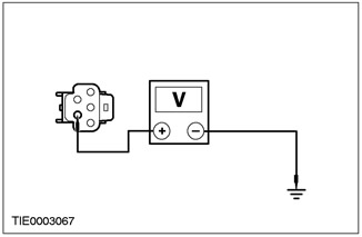
A1: CHECKING THE DRIVER'S DOOR WINDOW LIFT SWITCH LEDS |
|
|
1Enter the ON position. |
|
|
• Are the driver's door window switch LEDs illuminated? |
|
|
→ Yes |
|
|
CHECK the customer complaint. |
|
|
→ No |
|
|
3-door, 5-door and station wagon Go to A2 4-door version: REPAIR electrical circuit 15 - DA5 (green-orange). CHECK the correct operation of the system. |
|
|
A2: CHECKING THE REAR WINDOW WIPER MOTOR |
|
|
1Turn on the rear window wiper. |
|
|
• Does the rear window wiper work properly? |
|
|
→ Yes |
|
|
REPAIR electrical circuit 15 - DA5 (green/orange). CHECK correct system operation. |
|
|
→ No |
|
|
REPAIR electrical circuit 15 - KA28 (green/blue). CHECK for proper system operation. |
|
PINPOINT TEST B: ONE POWER WINDOW DOES NOT WORK - POWER WINDOWS ON FRONT AND REAR DOORS
|
STATES |
DETAILS/RESULTS/ACTIONS |
|
B1: CHECKING THE IGNITION VOLTAGE IN THE INOPERATING WINDOW REGULATOR SWITCH |
|
|
NOTE:Make sure the rear window switch lock is not engaged. |
|
|
1Enter the ON position. |
|
|
• Is the LED for the inoperative window switch on? |
|
|
→ Yes |
|
|
Go to B2 |
|
|
→ No |
|
|
Go to B6 |
|
|
B2: CHECKING IF A NON-FUNCTIONAL WINDOW CAN BE CONTROLLED USING THE WINDOW SWITCH LOCATED ON THE DRIVER'S DOOR |
|
|
1Operate the window switch located on the driver's door. |
|
|
• Does the non-working window operate properly? |
|
|
→ Yes |
|
|
Driver's Door Window Regulator, CHECK customer complaint. All Passenger Door Window Regulators, Go to B3 |
|
|
→ No |
|
|
Go to B8 |
|
|
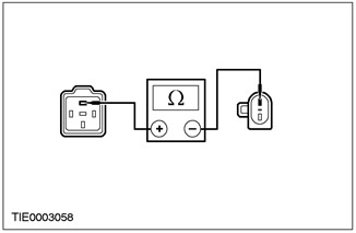
B3: CHECKING CONTINUITY OF THE ELECTRICAL CIRCUIT BETWEEN THE INOPERATIVE WINDOW REGULATOR SWITCH AND THE WINDOW UP MOTOR |
|
|
1Disconnect C735, C736 or C737 of the inoperative window motor. |
|
|
2Disconnect C485, C482 or C483 of the inoperative window switch. |
|
|
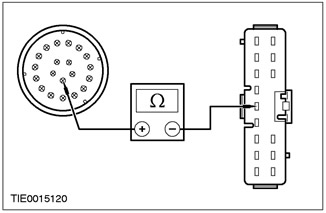
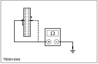
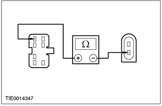
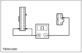
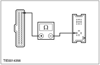
3Measure the resistance between pin 5 of connector C485 of the inoperative front passenger power window switch, circuit 31S - AJ55B (RD/BLK) and pin 3 of connector C735 of the power window motor, circuit 31S - AJ55A (RD/BLK), harness side; or between pin 5 of connector C482 of inoperative left rear door window switch, circuit 31S - AJ46B (black/white), and pin 3 of connector C736 of window lift motor, circuit 31S - AJ46A (black/white), harness side; or between pin 5 of connector C483 of the inoperative right rear door window switch, circuit 31S - AJ46B (black/white), and pin 3 of connector C737 of the window lift motor, circuit 31S - AJ46A (black/white), harness side. |
|
• Resistance less than 5 ohms? |
|
|
→ Yes |
|
|
Go to B4 |
|
|
→ No |
|
|
REPAIR electrical circuit 31S - AJ55B (red/black); or electrical circuit 31S - AJ46B (black and white). CHECK the correct operation of the system. |
|
|
B4: CHECKING CONTINUITY OF THE ELECTRICAL CIRCUIT BETWEEN THE INOPERATIVE WINDOW REGULATOR SWITCH AND THE WINDOW DOWN MOTOR |
|
|
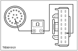
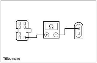
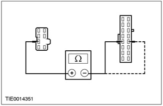
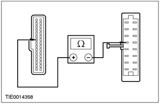
1Measure the resistance between pin 2 of the inoperative front passenger power window switch C485, circuit 31S - AJ54B (BK/GN) and pin 4 of the power window motor C735, circuit 31S - AJ54A (BK/GN), harness side; or between pin 2 of connector C482 of inoperative left rear door window switch, circuit 31S - AJ63B (black/green), and pin 4 of connector C736 of window lift motor, circuit 31S - AJ63A (black/blue), harness side; or between pin 2 of connector C483 of the inoperative right rear door window switch, circuit 31S - AJ63B (black/blue), and pin 4 of connector C737 of the window lift motor, circuit 31S - AJ63A (black/blue), on the wiring side. |
|
• Resistance less than 5 ohms? |
|
|
→ Yes |
|
|
Go to B5 |
|
|
→ No |
|
|
REPAIR electrical circuit 31S - AJ54B (black-green); or electrical circuit 31S - AJ63B (black-green); or electrical circuit 31S - AJ63B (black and blue). CHECK that the system is working properly. |
|
|
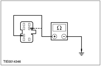
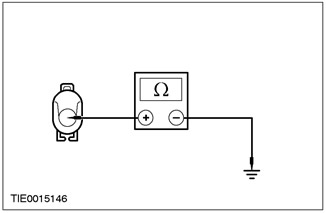
B5: CHECKING THE GROUND CIRCUIT OF THE INOPERATING WINDOW REGULATOR MOTOR |
|

|
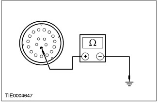
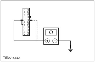
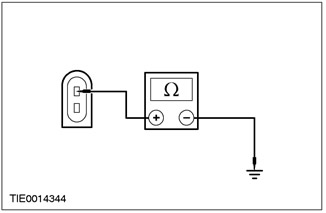
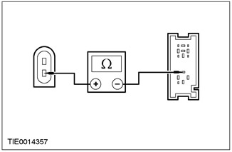
1Measure the resistance between pin 8 of the inoperative driver's door window lift motor connector C734, circuit 31 - AJ26 (black), harness side, and ground; or pin 8 of connector C735 of the inoperative front passenger door window lift motor, electrical circuit 31 - AJ27 (black), on the wiring side, and "ground"; or pin 8 of connector C736 of the inoperative left rear door window lift motor, electrical circuit 31 - AJ31 (black), on the wiring side, and "ground"; or pin 8 of connector C737 of the inoperative right rear door window lift motor, electrical circuit 31 - AJ31 (black), on the wiring side, and ground. |
|
• Resistance less than 5 ohms? |
|
|
→ Yes |
|
|
CHECK the customer complaint. |
|
|
→ No |
|
|
REPAIR electrical circuit 31 - AJ26 (black); or electrical circuit 31 - AJ27 (black); or electrical circuit 31 - AJ31 (black). CHECK that the system is operating correctly. |
|
|
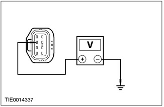
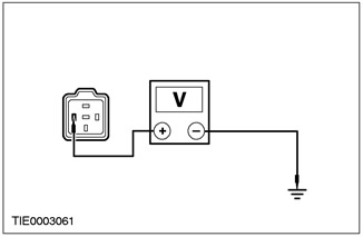
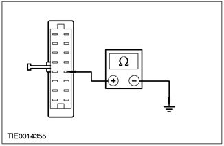
B6: CHECKING THE VOLTAGE IN THE ELECTRICAL CIRCUIT OF THE INOPERATIVE WINDOW REGULATOR SWITCH |
|
|
1Enter the OFF position. |
|
|
2Disconnect C484, C485, C482, C483 of the inoperative window switch. |
|
|
3Enter the ON position. |
|
|
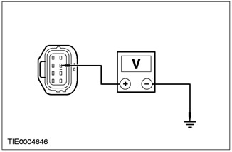
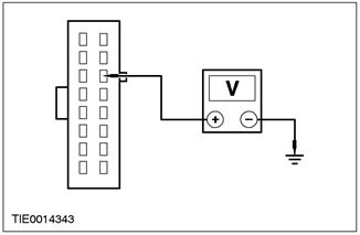
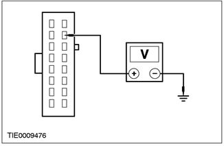
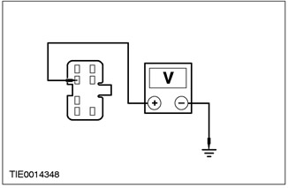
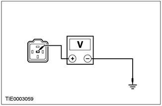
4Measure the voltage between pin 13 of the inoperative driver's door window switch connector C484, circuit 15 - LH14 (GN/YE), harness side and ground; or between pin 1 of connector C485 of the inoperative front passenger door window switch, electrical circuit 15 - LH31 (green/blue), harness side, and ground; or between pin 1 of connector C482 of the inoperative left rear door window switch, electrical circuit 15 - LH36 (red/green), harness side, and ground; or between pin 1 of connector C483 for inoperative right rear door window power window switch, circuit 15 - LH36 (red/green), harness side, and ground (passenger window shown). |
|
• Is the voltage greater than 10 V? |
|
|
→ Yes |
|
|
Go to B7 |
|
|
→ No |
|
|
Go to B14 |
|
|
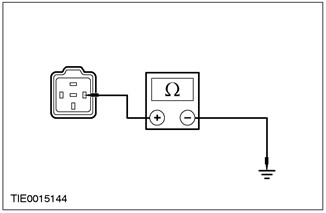
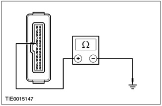
B7: CHECKING THE GROUND CIRCUIT OF THE INOPERATIVE WINDOW REGULATOR SWITCH |
|
|
1Enter the OFF position. |
|
|
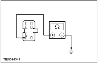
2Measure the resistance between pin 4 of the inoperative driver's door window switch connector C484, circuit 31 - AJ7 (Black), harness side and ground; or between pin 6 of connector C485 of the inoperative front passenger door window switch, electrical circuit 31 - AJ18 (black), harness side, and ground; or between pin 6 of connector C482 of the inoperative left rear door window switch, electrical circuit 31S - AJ32 (black-orange), on the wiring side, and ground; or between pin 6 of connector C483 of the inoperative right rear door window switch, circuit 31S - AJ32 (black/orange), harness side, and ground (driver's window shown). |
|
• Resistance less than 5 ohms? |
|
|
→ Yes |
|
|
REPAIR electrical circuit 32-AJ26 (white). |
|
|
→ No |
|
|
REPAIR electrical circuit 31 - AJ7 (black); or electrical circuit 31 - AJ18 (black); or electrical circuit 31S - AJ32 (black-orange) or 31S - AJ14 (black-orange); or electrical circuit 31S - AJ32 (black/orange) or 31S - AJ24 (black/yellow). CHECK that the system is working properly. |
|
|
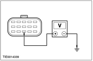
B8: CHECKING THE VOLTAGE IN THE DOOR CONNECTOR WITH THE WINDOW LIFT NOT WORKING |
|
|
1Enter the OFF position. |
|
|
2Disconnect C42, C44, C45 or C46 of the door with the inoperative window. |
|
|
3Enter the ON position. |
|
|
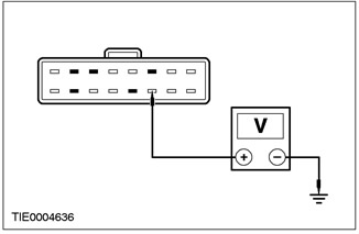
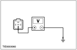
4Measure the voltage between pin 9 of connector C42 on the driver's door with the inoperative window, circuit 29 - AJ26 (yellow/orange), harness side, and ground; or pin 9 of connector C44 on the front passenger door with the inoperative window lifter, electrical circuit 29 - AJ27 (orange-white), on the wiring side, and "ground"; or pin 9 of connector C45 on the left rear door with the inoperative window lifter, electrical circuit 29 - AJ13 (orange-blue), on the wiring side, and "ground"; or pin 9 of connector C46 on the right rear door with the inoperative window lifter, electrical circuit 29 - AJ23 (orange-white), on the wiring side, and ground. |
|
• Is the voltage greater than 10 V? |
|
|
→ Yes |
|
|
Go to B9 |
|
|
→ No |
|
|
REPAIR electrical circuit 29 - AJ26 (yellow-orange); or electrical circuit 29 - AJ27 (orange-white); or electrical circuit 29 - AJ13 (orange-blue); or electrical circuit 29 - AJ23 (orange/white). CHECK that the system is operating correctly. |
|
|
B9: CHECKING THE GROUND CIRCUIT OF THE INOPERATING WINDOW REGULATOR MOTOR |
|
|
1Enter the OFF position. |
|
|
2Disconnect C734, C735, C736 or C737 of the inoperative window motor. |
|
|
3Measure the resistance between pin 8 of the inoperative driver's door window lift motor connector C734, circuit 31 - AJ26 (black), harness side, and ground; or pin 8 of connector C735 of the inoperative front passenger door window lift motor, electrical circuit 31 - AJ27 (black), on the wiring side, and "ground"; or pin 8 of connector C736 of the inoperative left rear door window lift motor, electrical circuit 31 - AJ31 (black), on the wiring side, and "ground"; or pin 8 of connector C737 of the inoperative right rear door window lift motor, electrical circuit 31 - AJ31 (black), on the wiring side, and ground. |
|
• Resistance less than 5 ohms? |
|
|
→ Yes |
|
|
Go to B10 |
|
|
→ No |
|
|
REPAIR electrical circuit 31 - AJ26 (black); or electrical circuit 31 - AJ27 (black); or electrical circuit 31 - AJ31 (black). CHECK that the system is operating correctly. |
|
|
B10: CHECKING THE VOLTAGE IN THE PLUG CONNECTOR OF THE INOPERATING WINDOW REGULATOR MOTOR |
|
|
1Connect C42, C44, C45 or C46 of the inoperative window motor. |
|
|
2Enter the ON position. |
|
|
3Measure the voltage between the inoperative driver's door window motor C734 pin 7, circuit 29 - AJ26 (YE/OG), harness side and ground; or pin 7 of connector C735 of the inoperative front passenger door window lift motor, electrical circuit 29 - AJ27 (orange/white), on the wiring side, and "ground"; or pin 7 of connector C736 of the inoperative left rear door window lift motor, electrical circuit 29 - AJ31 (orange-blue), from the wiring side, and "ground"; or pin 7 of connector C737 of the inoperative right rear door window lift motor, electrical circuit 29 - AJ31 (orange-blue), from the wiring side, and ground. |
|
• Is the voltage greater than 10 V? |
|
|
→ Yes |
|
|
Go to B11 |
|
|
→ No |
|
|
REPAIR electrical circuit 29 - AJ26 (yellow-orange); or electrical circuit 29 - AJ27 (orange-white); or electrical circuit 29 - AJ31 (orange/blue). CHECK that the system is operating correctly. |
|
|
B11: CHECKING THE VOLTAGE IN THE ELECTRICAL CIRCUIT OF THE GLASS UP MOTOR OF THE INOPERATING WINDOW REGULATOR |
|
|
1Enter the OFF position.inscription |
|
|
2Turn the inoperative window motor switch to the window up position. |
|
|
3Measure the resistance between pin 3 of connector C734 of the inoperative driver's door window lift motor, circuit 31S - AJ41 (red/black) - left-hand drive version ([black/orange] - right-hand drive version), wiring side, and ground; or pin 3 of connector C735 of the inoperative front passenger door window lift motor, electrical circuit 31S - AJ55A (red-black), on the wiring side, and "ground"; or pin 3 of connector C736 of the inoperative left rear door window lift motor, electrical circuit 31S - AJ46A (black and white), on the wiring side, and "ground"; or pin 3 of connector C737 of the inoperative right rear door window lift motor, electrical circuit 31S - AJ46A (black and white), on the wiring side, and ground. |
|
• Resistance less than 5 ohms? |
|
|
→ Yes |
|
|
Go to B12 |
|
|
→ No |
|
|
REPAIR electrical circuit 31S - AJ41 (red/black) - left hand drive version ([black/orange] - right hand drive version); or electrical circuit 31S - AJ55A (red-black) or 31S - AJ55B (red-black); or electrical circuit 31S - AJ46A (red-black); or electrical circuit 31S - AJ46A (black and white) or 31S - AJ46B (black and white). CHECK that the system is working properly. |
|
|
B12: CHECKING THE VOLTAGE IN THE ELECTRICAL CIRCUIT OF THE WINDOW DOWN MOTOR OF THE INOPERATING WINDOW REGULATOR |
|
|
1Turn the inoperative window motor switch to the window down position. |
|
|
2Measure the resistance between pin 4 of connector C734 of the inoperative driver's door window lift motor, circuit 31S - AJ40 (black/green) - left-hand drive version ([black/blue] - right-hand drive version), harness side and ground; or pin 4 of connector C735 of the inoperative front passenger door window lift motor, electrical circuit 31S - AJ54A (black-green), on the wiring side, and "ground"; or pin 4 of connector C736 of the inoperative left rear door window lift motor, electrical circuit 31S - AJ63A (black and blue), from the wiring side, and "ground"; or pin 4 of connector C737 of the inoperative right rear door window lift motor, electrical circuit 31S - AJ63A (black and blue), from the wiring side, and ground. |
|
• Resistance less than 5 ohms? |
|
|
→ Yes |
|
|
Go to B13 |
|
|
→ No |
|
|
REPAIR electrical circuit 31S - AJ40 (black/green) - left hand drive version ([black/blue] - right hand drive version); or electrical circuit 31S - AJ54A (black-green) or 31S - AJ54B (black-green); or electrical circuit 31S - AJ63A (black/blue) or electrical circuit 31S - AJ63B (black/green). CHECK that the system is operating correctly. |
|
|
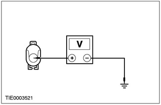
B13: CHECKING THE VOLTAGE IN THE MOTOR OF THE INOPERATING WINDOW REGULATOR |
|
|
1Measure the voltage between the inoperative driver's door window motor C734 pin 2, circuit 15 - AJ26 (GN/YE), harness side and ground; or pin 2 of connector C735 of the inoperative front passenger door window lift motor, electrical circuit 31S - AJ27A (white-green), on the wiring side, and "ground"; or pin 2 of connector C736 of the inoperative left rear door window lift motor, electrical circuit 31S - AJ31A (green-blue), from the wiring side, and "ground"; or pin 2 of connector C737 of the inoperative right rear door window lift motor, electrical circuit 31S - AJ31A (green-blue), from the wiring side, and ground. |
|
• Is the voltage greater than 10 V? |
|
|
→ Yes |
|
|
INSTALL a new electric motor. CHECK the system for proper operation. |
|
|
→ No |
|
|
REPAIR electrical circuit 15 - AJ26A (yellow-green); or electrical circuit 31S - AJ27A (white-green) or 31S - AJ54B (black-green); or electrical circuit 31S - AJ31A (green-blue). CHECK the correct operation of the system. |
|
|
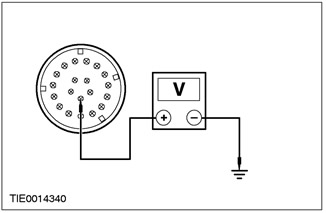
B14: CHECKING THE VOLTAGE IN THE DOOR CONNECTOR WITH THE POWER WINDOW INOPERATIVE |
|
|
1Disconnect C42, C44, C45 or C46 on the door with the inoperative window. |
|
|
2Measure the voltage between pin 15 of connector C42 on the driver's door with the inoperative window, circuit 15 - AJ26 (yellow/green) - left-hand drive version (circuit 15 - AJ27 [white/green] - right-hand drive version), A-pillar side, and ground; or pin 15 of connector C44 on the front passenger door with the inoperative window lifter, electrical circuit 15 - AJ27 (white-green) - left-hand drive version (electrical circuit 15 - AJ26 [yellow-green] - right-hand drive version), on the A-pillar side, and ground; or pin 13 of connector C45 on the left rear door with the inoperative window lifter, electrical circuit 15 - AJ13 (green-blue), on the B-pillar side, and ground; or pin 13 of connector C46 on the right rear door with the inoperative window lifter, electrical circuit 15 - AJ13 (green-blue), on the B-pillar side, and ground (B-pillar shown). |
|
• Is the voltage greater than 10 V? |
|
|
→ Yes |
|
|
REPAIR electrical circuit 15 - AJ26 (yellow/green) door side or electrical circuit 15 - LH14 (yellow/green); or electrical circuit 15 - AJ27 (white-green) or electrical circuit 15 - LH31 (green-blue); or electrical circuit 15 - AJ31 (green-blue) or 15 - LH36 (red-green). CHECK that the system is working correctly. |
|
|
→ No |
|
|
REPAIR electrical circuit 15 - AJ26 (yellow/green), A-pillar side; or electrical circuit 15 - AJ27 (white-green); or electrical circuit 15 - AJ13 (green-blue). CHECK that the system is working correctly. |
|
PINPOINT TEST C: GENERAL LOCK FUNCTION DOES NOT WORK
|
STATES |
DETAILS/RESULTS/ACTIONS |
|
NOTE:Make sure all window motors have been initialized. |
|
|
C1: CHECK THE CONNECTION OF THE CENTRAL TIMER MODULE TO THE CENTRAL SECURITY MODULE. |
|
|
1Check the lock button on the remote control. |
|
|
• Do the interior lights go out? |
|
|
→ Yes |
|
|
Go to C2 |
|
|
→ No |
|
|
REPAIR electrical circuit(s). REFER to Section 419 - 10. |
|
|
C2: CHECKING THE VOLTAGE IN THE CONNECTOR OF THE INOPERATING WINDOW REGULATOR |
|
|
1Disconnect C42, C44, C45 or C46 on the door with the inoperative window. |
|
|
2Measure the voltage between pin 16 of connector C42 on the driver's door with the inoperative window, circuit 8 - AJ42 (WH/GN), A-pillar side, and ground (shown); or pin 16 of connector C44 on the front passenger door with the inoperative window lifter, electrical circuit 8 - AJ56 (white-green), on the A-pillar side, and ground; or pin 11 of connector C45 on the left rear door with the inoperative window lifter, electrical circuit 8 - AJ59 (white-green), on the B-pillar side, and ground; or pin 11 of connector C46 on the right rear door with the inoperative window lifter, electrical circuit 8 - AJ62 (white-green), on the B-pillar side, and ground. |
|
• Is the voltage greater than 10 V? |
|
|
→ Yes |
|
|
Go to C3 |
|
|
→ No |
|
|
Go to C4 |
|
|
C3: CHECKING THE VOLTAGE IN THE MOTOR OF THE INOPERATING WINDOW REGULATOR |
|
|
1Connect the plug to the door with the inoperative window. |
|
|
2Disconnect the electrical connector of the inoperative window lift motor. |
|
|
3Measure the voltage between pin 6 of the inoperative driver's door window motor C734, circuit 8 - AJ42 (WH/GN), harness side, and ground; or pin 6 of connector C735 of the inoperative passenger door window lift motor, electrical circuit 8 - AJ56 (white-green), on the wiring side, and "ground"; or pin 6 of connector C737 of the inoperative left rear door window lift motor, electrical circuit 8 - AJ65 (white-green), on the wiring side, and "ground"; or pin 6 of connector C736 of the inoperative right rear door window lift motor, electrical circuit 8 - AJ65 (white-green) or 8 - AJ65 (white-green), on the wiring side, and ground. |
|
• Is the voltage greater than 10 V? |
|
|
→ Yes |
|
|
INSTALL a new motor. REFER to the procedure in this section: "Door Window Motor". CHECK for proper operation of the system. |
|
|
→ No |
|
|
REPAIR electrical circuit 8 - AJ42 (white-green); or 8 - AJ56 (white and green) or 8 - AJ65 (white and green). CHECK that the system is working correctly. |
|
|
C4: CHECKING FLOOR WIRING FOR SHORT TO GROUND" |
|
|
NOTE:The electrical circuit numbers change in splice S152. |
|
|
1Disconnect all door plug connectors: C42, C44, C45 and C46. |
|
|
2Disconnect the C1000 central timer module. |
|
|
3Measure the resistance between pin 16 of connector C42 on the driver's door, electrical circuit 8 - AJ42 (white/green), A-pillar side, and ground. |
|
• Resistance greater than 10,000 ohms? |
|
|
→ Yes |
|
|
Go to C5 |
|
|
→ No |
|
|
REPAIR Floor Harness Electrical Circuit 8 - AJ42 (White/Green); or 8 - AJ56 (white and green); or 8 - AJ59 (white and green); or 8 - AJ65 (white and green). CHECK that the system is working properly. |
|
|
C5: CHECKING CONTINUITY OF THE ELECTRICAL CIRCUIT BETWEEN THE DRIVER'S DOOR WINDOW PLUG AND THE CENTRAL JUNCTION BOX |
|
|
1Disconnect C15 from the central electrical junction box. |
|
|
2Measure the resistance between pin 16 of connector C42 on the driver's door, circuit 8 - AJ42 (green/white), A-pillar side and pin 11 of connector C15 on the central electrical box, circuit 8 - AA36 (white), harness side. |
|
• INSTALL a new relay. |
|
|
→ Yes |
|
|
Go to C6 |
|
|
→ No |
|
|
REPAIR circuit 8 - AA36 or 8 - AA36A (white). REPAIR circuit 32-AJ26 (white). |
|
|
C6: CHECKING CONTINUITY OF THE ELECTRICAL CIRCUIT BETWEEN THE DRIVER'S DOOR WINDOW PLUG AND THE CENTRAL SECURITY MODULE |
|
|
1Disconnect C451 from the central security module. |
|
|
2Measure the resistance between pin 16 of connector C42 on the driver's door, circuit 8 - AJ42 (green/white), A-pillar side and pin 14 of connector C451, circuit 8 - AA36 (white), harness side. |
|
• INSTALL a new switch. |
|
|
→ Yes |
|
|
CHECK the customer complaint. |
|
|
→ No |
|
|
REPAIR circuit 8 - AA36 (white). CHECK system operation for proper operation. |
|
PINPOINT TEST D: POWER WINDOWS DO NOT WORK ON ALL WINDOWS - POWER WINDOWS ON FRONT DOORS
|
STATES |
DETAILS/RESULTS/ACTIONS |
|
D1: CHECKING THE VOLTAGE IN THE WINDOW SWITCHES |
|
|
1Enter the ON position. |
|
|
• Do the power window switch LEDs light up? |
|
|
→ Yes |
|
|
Go to D2 |
|
|
→ No |
|
|
Go to D3 |
|
|
D2: CHECKING THE CONTINUITY OF THE DRIVER'S DOOR WINDOW REGULATOR SWITCH GROUND CIRCUIT |
|
|
1Enter the OFF position. |
|
|
2Disconnect C488 driver's door window switch. |
|
|
3Measure the resistance between pin 5 (left-hand drive) (or pin 13 (right-hand drive) of the driver's door window lift switch connector C488, circuit 31 - AJ7 (Black), harness side and ground. |
|
• INSTALL a new switch. |
|
|
→ Yes |
|
|
CHECK the customer complaint. |
|
|
→ No |
|
|
REPAIR electrical circuit 31 - AJ7 (black). CHECK for proper system operation. |
|
|
D3: CHECKING THE VOLTAGE IN THE DRIVER'S DOOR WINDOW REGULATOR SWITCH |
|
|
1Enter the OFF position. |
|
|
2Disconnect C488 driver's door window switch. |
|
|
3Enter the ON position. |
|
|
4Measure the voltage between driver's door window lift switch connector C488 pin 14, circuit 15 - LH14 (GN/YE), harness side and ground. |
|
• Is the voltage greater than 10 V? |
|
|
→ Yes |
|
|
CHECK the customer complaint. |
|
|
→ No |
|
|
Repair electrical circuit 15 LH14 (yellow/green). CHECK for proper system operation. |
|
PINPOINT TEST E: ONE WINDOW WINDOW ELECTRIC DRIVE DOES NOT WORK - DRIVER SIDE
|
STATES |
DETAILS/RESULTS/ACTIONS |
|
E1: CHECKING THE VOLTAGE IN THE DRIVER'S DOOR WINDOW REGULATOR SWITCH |
|
|
1Enter the ON position. |
|
|
• Is the driver's door window power switch LED on? |
|
|
→ Yes |
|
|
Go to E2 |
|
|
→ No |
|
|
Go to E7 |
|
|
E2: CHECKING THE SWITCHING VOLTAGE IN THE DRIVER'S DOOR WINDOW REGULATOR SWITCH |
|
|
1Operate the front passenger window control switch located on the driver's door. |
|
|
• Is the front passenger door window controlled by a switch located on the driver's door? |
|
|
→ Yes |
|
|
Go to E3 |
|
|
→ No |
|
|
Go to E9 |
|
|
E3: CHECKING THE ONE-TOUCH OPENING FUNCTION RELAY" |
|
|
1Operate the driver's door window switch to the first detent position. |
|
|
• Does the one-touch opening function relay operate with a distinct sound? |
|
|
→ Yes |
|
|
Go to E4 |
|
|
→ No |
|
|
Go to E10 |
|
|
E4: CHECKING THE VOLTAGE IN THE ELECTRICAL CIRCUIT OF THE DRIVER'S DOOR WINDOW DOWN MOTOR |
|
|
1Enter the OFF position. |
|
|
2Disconnect C782 driver's door window lift motor. |
|
|
3Enter the ON position. |
|
|
4Operate the driver's door window switch to the first detent in the down direction. |
|
|
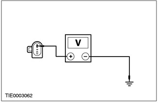
5Measure the voltage between pin 2 of the driver's door window lift motor connector C782, circuit 32 - AJ26 (white), and ground. |
|
• Is the voltage greater than 10 V? |
|
|
→ Yes |
|
|
Go to E5 |
|
|
→ No |
|
|
Go to E13 |
|
|
E5: CHECKING THE VOLTAGE IN THE ELECTRICAL CIRCUIT OF THE DRIVER'S DOOR WINDOW UP MOTOR |
|
|
1Operate the driver's door window switch to the first detent in the up direction. |
|
|
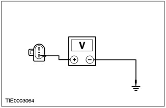
2Measure the voltage between driver's door window lift motor connector C782 pin 1, circuit 32 - AJ26 (Yellow), and ground. |
|
• Is the voltage greater than 10 V? |
|
|
→ Yes |
|
|
Go to E6 |
|
|
→ No |
|
|
REPAIR electrical circuit 33 - AJ26 (yellow). CHECK for proper system operation. |
|
|
E6: CHECKING THE INTEGRITY OF THE ELECTRICAL GROUND CIRCUIT OF THE DRIVER'S DOOR WINDOW MOTOR |
|
|
1Enter the OFF position. |
|
|
2Measure the resistance between pin 2 of the driver's door window lift motor connector C782, circuit 33 - AJ26 (white), and ground. |
|
• CHECK the customer complaint. |
|
|
→ Yes |
|
|
INSTALL a new motor. REFER to the procedure in this section: "Door Window Motor". CHECK for proper operation of the system. |
|
|
→ No |
|
|
INSTALL a new one-touch open relay. CHECK that the system is working properly. |
|
|
E7: CHECKING THE VOLTAGE IN THE DRIVER'S DOOR WINDOW REGULATOR SWITCH |
|
|
1Enter the OFF position. |
|
|
2Disconnect C488 driver's door window switch. |
|
|
3Enter the ON position. |
|
|
4Measure the voltage between driver's door window lift switch connector C488 pin 14, circuit 15 - LH14 (GN/YE) and ground. |
|
• Is the voltage greater than 10 V? |
|
|
→ Yes |
|
|
Go to E8 |
|
|
→ No |
|
|
Repair electrical circuit 15 - LH14 (yellow/green) CHECK system operation for proper operation. |
|
|
E8: CHECKING THE GROUND CIRCUIT OF THE DRIVER'S DOOR WINDOW REGULATOR SWITCH |
|
|
1Enter the OFF position. |
|
|
2Measure the resistance between pin 5 (LHD) (pin 13 (RHD) of the driver's door window switch connector C488, circuit 31 - AJ7 (Black), and ground. |
|
• Resistance less than 5 ohms? |
|
|
→ Yes |
|
|
CHECK the customer complaint. |
|
|
→ No |
|
|
REPAIR electrical circuit 31 - AJ7 (black). CHECK for proper system operation. |
|
|
E9: CHECKING THE VOLTAGE IN THE DRIVER'S DOOR WINDOW REGULATOR SWITCH |
|
|
1Enter the OFF position. |
|
|
2Disconnect C488 driver's door window switch. |
|
|
3Enter the ON position. |
|
|
4Measure the voltage between driver's door window lift switch connector C488 pin 15, circuit 15 - AJ7 (GN/BU), harness side and ground. |
|
• Is the voltage greater than 10 V? |
|
|
→ Yes |
|
|
CHECK the customer complaint. |
|
|
→ No |
|
|
REPAIR electrical circuit 15-AJ7 (green/blue). CHECK for proper system operation. |
|
|
E10: CHECKING THE SWITCHING VOLTAGE IN THE ONE-TOUCH OPENING RELAY" |
|
|
1Enter the OFF position. |
|
|
2Disconnect C738 one touch open relay. |
|
|
3Enter the ON position. |
|
|
4Operate the driver's door window switch to the first detent position in the down direction. |
|

|
5Measure the voltage between pin 3 of connector C738 one-touch opening relay00, circuit 15S - AJ40 (green/blue), harness side, and ground. |
|
• Is the voltage greater than 10 V? |
|
|
→ Yes |
|
|
Go to E11 |
|
|
→ No |
|
|
REPAIR electrical circuit 15S - AJ40 (green/blue). CHECK for proper system operation. |
|
|
E11: CHECKING THE IGNITION VOLTAGE SUPPLIED TO THE ONE-TOUCH OPENING RELAY" |
|
|
1Measure the voltage between pin 2 of connector C738 one-touch opening relay, circuit 15 - AJ15 (black/green), harness side, and ground. |
|
• Is the voltage greater than 10 V? |
|
|
→ Yes |
|
|
Go to E12 |
|
|
→ No |
|
|
REPAIR electrical circuit 15 - AJ15 (black/green). CHECK for proper system operation. |
|
|
E12: CHECKING THE CONTINUITY OF THE ELECTRICAL CIRCUIT BETWEEN THE ONE-TOUCH OPENING RELAY AND THE GROUND" |
|
|
1Enter the OFF position. |
|
|
2Measure the resistance between pin 1 of connector C738 one-touch open relay, circuit 31 - AJ15 (black), harness side and ground. |
|
• Resistance less than 5 ohms? |
|
|
→ Yes |
|
|
INSTALL a new one-touch open relay. CHECK that the system is working properly. |
|
|
→ No |
|
|
REPAIR electrical circuit 31 - AJ15 (black). CHECK for proper system operation. |
|
|
E13: CHECKING THE CONTINUITY OF THE ELECTRICAL CIRCUIT BETWEEN THE DRIVER'S WINDOW MOTOR AND THE ONE-TOUCH OPENING RELAY. |
|
|
1Enter the OFF position. |
|
|
2Disconnect C782 driver's door window lift motor. |
|
|
3Measure the resistance between pin 2 of connector C782 driver's power window motor, circuit 32 - AJ26 (white), harness side and pin 5 of connector C738 one-touch open relay, circuit 32 - AJ26 (white), harness side. |
|
• Resistance less than 5 ohms? |
|
|
→ Yes |
|
|
INSTALL a new one-touch open relay. CHECK that the system is operating correctly. CHECK that the system is operating correctly. |
|
|
→ No |
|
|
REPAIR electrical circuit 32 - AJ26 (white). CHECK for proper system operation. |
|
PINPOINT TEST F: ONE WINDOW POWER WINDOW DOES NOT WORK - PASSENGER SIDE
|
STATES |
DETAILS/RESULTS/ACTIONS |
|
F1: CHECKING THE VOLTAGE IN THE PASSENGER DOOR WINDOW REGULATOR SWITCH |
|
|
1Enter the ON position. |
|
|
• Is the passenger door window power switch LED on? |
|
|
→ Yes |
|
|
Go to F2 |
|
|
→ No |
|
|
Go to F5 |
|
|
F2: CHECKING THE PASSENGER DOOR WINDOW GROUND CIRCUIT |
|
|
1Enter the OFF position. |
|
|
2Disconnect C489 passenger door window switch. |
|
|
3Measure the resistance between pin 3 of the passenger power window switch connector C489, circuit 32 - AJ18 (WH/PUP), harness side and ground; and between pin 6 of connector C489 of the passenger door window lift switch, electrical circuit 33 - AJ18 (yellow-violet), on the wiring side, and ground. |
|
• Is the resistance less than 5 ohms in all cases? |
|
|
→ Yes |
|
|
Go to F3 |
|
|
→ No |
|
|
Go to F7 |
|
|
F3: CHECKING CONTINUITY OF THE ELECTRICAL CIRCUIT BETWEEN THE PASSENGER DOOR WINDOW REGULATOR SWITCH AND THE CORRESPONDING WINDOW REGULATOR MOTOR |
|
|
1Disconnect the passenger door window motor. |
|
|
2Measure the resistance between pin 1 of passenger power window switch C489, circuit 33 - AJ17 (YE/VI) (left-hand drive version) (circuit 33 - AJ6 [YE], right-hand drive version), harness side and pin 1 of passenger power window motor C783, circuit 33 - AJ17 (YE/VI) (left-hand drive version) (circuit 33 - AJ6 [YE], right-hand drive version), harness side. |
|
• Resistance less than 5 ohms? |
|
|
→ Yes |
|
|
Go to F4 |
|
|
→ No |
|
|
REPAIR circuit 33 - AJ17 (Yellow/Purple) (LHD version) (circuit 33 - AJ6 [Yellow] RHD version). CHECK for proper system operation. |
|
|
F4: CHECKING CONTINUITY OF THE ELECTRICAL CIRCUIT BETWEEN THE PASSENGER DOOR WINDOW SWITCH AND THE ASSOCIATED MOTOR |
|
|
1Measure the resistance between pin 7 of connector C489 passenger power window switch, circuit 32 - AJ17 (WH/PU) (left-hand drive version) (circuit 32 - AJ6 [WH], right-hand drive version), harness side and pin 2 of connector C783 passenger power window motor, circuit 32 - AJ17 (WH/PU), left-hand drive version (circuit 32 - AJ6 [WH], right-hand drive version), harness side. |
|
• Resistance less than 5 ohms? |
|
|
→ Yes |
|
|
INSTALL a new window motor. CHECK the system for proper operation. |
|
|
→ No |
|
|
REPAIR circuit 32 - AJ17 (white/purple) (left-hand drive version) (circuit 32 - AJ6 [white], right-hand drive version). CHECK for proper system operation. |
|
|
F5: CHECKING THE VOLTAGE IN THE PASSENGER DOOR WINDOW REGULATOR SWITCH |
|
|
1Enter the OFF position. |
|
|
2Disconnect C489 passenger door window switch. |
|
|
3Enter the ON position. |
|
|
4Measure the voltage between passenger power window switch connector C489 pin 2, circuit 15 - AJ18 (WH/GN), harness side and ground. |
|
• Is the voltage greater than 10 V? |
|
|
→ Yes |
|
|
Go to F6 |
|
|
→ No |
|
|
REPAIR circuit 15-AJ18 (white/green). CHECK for proper system operation. |
|
|
F6: CHECK PASSENGER DOOR WINDOW SWITCH GROUND CIRCUIT |
|
|
1Measure the resistance between pin 4 of passenger power window switch connector C489, circuit 31 - LH31 (Black), harness side and ground. |
|
• Resistance less than 5 ohms? |
|
|
→ Yes |
|
|
CHECK the customer complaint. |
|
|
→ No |
|
|
REPAIR electrical circuit 31-LH31 (black). CHECK for proper system operation. |
|
|
F7: CHECKING CONTINUITY OF ELECTRICAL CIRCUIT BETWEEN DRIVER WINDOW SWITCH AND PASSENGER WINDOW SWITCH |
|
|
1Measure the resistance between pin 1 of connector C488 of the driver's door window lifter switch, electrical circuit 33-AJ18 (yellow-purple) (left-hand drive version) (pin 9, right-hand drive version), and pin 6 of connector C489 of the passenger door window lifter switch, electrical circuit 33-AJ18 (yellow-purple). |
|
• Resistance less than 5 ohms? |
|
|
→ Yes |
|
|
Go to F8 |
|
|
→ No |
|
|
REPAIR circuit 33-AJ18 (yellow/purple). CHECK for proper system operation. |
|
|
F8: CHECKING CONTINUITY OF ELECTRICAL CIRCUIT BETWEEN DRIVER WINDOW SWITCH AND PASSENGER WINDOW SWITCH |
|
|
1Measure the resistance between pin 4 of the driver's door window switch C488, circuit 32 - AJ18 (WH/PU), (LHD version) (pin 12, RHD version) and pin 3 of the passenger's door window switch C489, circuit 32 - AJ18 (WH/PU). |
|
• Resistance less than 5 ohms? |
|
|
→ Yes |
|
|
CHECK the customer complaint. |
|
|
→ No |
|
|
REPAIR electrical circuit 32 - AJ18 (white/purple). CHECK for proper system operation. |
|
PINPOINT TEST G: ONE-TOUCH OPENING FUNCTION DOESN'T WORK"
|
STATES |
DETAILS/RESULTS/ACTIONS |
|
G1: CHECKING THE OPERATION OF THE ONE-TOUCH OPENING RELAY" |
|
|
1Enter the ON position. |
|
|
2Operate the driver's door window switch to the second detent position in the down direction. |
|
|
• Does the relay click? |
|
|
→ Yes |
|
|
Go to G2 |
|
|
→ No |
|
|
Go to G3 |
|
|
G2: CHECKING THE IGNITION VOLTAGE SUPPLIED TO THE ONE-TOUCH OPENING RELAY" |
|
|
1Enter the OFF position. |
|
|
2Disconnect C738 one touch opening relay.. |
|
|
3Enter the ON position. |
|
|
4Operate the driver's door window switch to the second detent position in the down direction. |
|
|
5Measure the voltage between pin 4 of connector C738 one-touch open relay, circuit 15S - AJ42 (black/green), harness side, and ground. |
|
• INSTALL a new one-touch open relay. CHECK that the system is operating correctly. |
|
|
→ Yes |
|
|
INSTALL a new one-touch open relay. CHECK that the system is working properly. |
|
|
→ No |
|
|
REPAIR electrical circuit 15S - AJ42 (black/green). CHECK for proper system operation. |
|
|
G3: CHECKING THE VOLTAGE IN THE ONE-TOUCH OPENING RELAY" |
|
|
1Disconnect C738 one touch open relay. |
|
|
2Enter the ON position. |
|
|
3Operate the driver's door window switch to the second detent position in the down direction. |
|
|
4Measure the voltage between pin 3 of connector C738 one-touch opening relay, circuit 15S - AJ40 (green/blue), harness side, and ground. |
|
• Is the voltage greater than 10 V? |
|
|
→ Yes |
|
|
INSTALL a new one-touch open relay. CHECK that the system is operating correctly. CHECK that the system is operating correctly. |
|
|
→ No |
|
|
REPAIR electrical circuit 15S - AJ40 (green/blue). CHECK for proper system operation. |
|
PINPOINT TEST H: DE-ICING SYSTEM NOT WORKING
|
STATES |
DETAILS/RESULTS/ACTIONS |
|
NOTE:This symptom also applies to the heated mirror and heated windshield de-icing system. If the heated rear window and heated outside mirrors do not work, GO to H1; if the heated windshield does not work, GO to H14. |
|
|
H1: PRESS THE REAR WINDOW DEHEATER SWITCH. |
|
|
1Enter the ON position. |
|
|
2Operate the rear window defroster switch |
|
|
• Does the rear window defroster relay click? |
|
|
→ Yes |
|
|
Go to H2 |
|
|
→ No |
|
|
Go to H4 |
|
|
H2: CHECKING THE OPERATION OF THE EXTERIOR MIRRORS |
|
|
1Operate the rear window defroster switch. |
|
|
• Do the heated outside mirrors work properly? |
|
|
→ Yes |
|
|
Go to H3 |
|
|
→ No |
|
|
Go to H7 |
|
|
H3: CHECKING THE OPERATION OF THE REAR WINDOW HEATING CIRCUIT |
|
|
1Operate the rear window defroster switch. |
|
|
• Does the rear window defroster work properly? |
|
|
→ Yes |
|
|
CHECK the customer complaint. |
|
|
→ No |
|
|
Go to H10 |
|
|
H4: CHECKING THE IGNITION VOLTAGE IN THE REAR WINDOW HEATING RELAY |
|
|
1Enter the OFF position. |
|
|
2Disconnect C1025 rear window defroster relay. |
|
|
3Enter the ON position. |
|
|
4Operate the rear window defroster switch. |
|
|
5Measure the voltage between pin 1 of the rear window defogger relay connector C1025, circuit 15 - DA1 (green/yellow), harness side, and ground. |
|
• Is the voltage greater than 10 V? |
|
|
→ Yes |
|
|
Go to H5 |
|
|
→ No |
|
|
REPAIR the central electrical box. CHECK the system for proper operation. |
|
|
H5: CHECKING CONTINUITY OF THE ELECTRICAL CIRCUIT BETWEEN THE REAR WINDOW DEHEATER RELAY AND THE CENTRAL TIMER MODULE |
|
|
1Enter the OFF position. |
|
|
2Measure the resistance between pin 2 of connector C1025 of the rear window defogger relay (CJB), harness side, and pin 4 of connector C1000 of the central timer module (CJB), harness side. |
|
• Resistance less than 5 ohms? |
|
|
→ Yes |
|
|
Go to H6 |
|
|
→ No |
|
|
REPAIR the central electrical box. CHECK the system for proper operation. |
|
|
H6: CHECKING THE INTEGRITY OF THE ELECTRICAL GROUNDING CIRCUIT OF THE CENTRAL TIMER MODULE |
|
|
1Operate the rear window defroster switch |
|
|
2Measure the resistance between pin 19 of the central timing module (CJB) connector C1000, harness side, and ground. |
|
• Resistance less than 5 ohms? |
|
|
→ Yes |
|
|
INSTALL a new rear window defroster relay. CHECK the system for proper operation. |
|
|
→ No |
|
|
Go to H12 |
|
|
H7: CHECKING THE VOLTAGE AT FUSE 51 (7.5A) CENTRAL JUNCTION BOX (CJB) |
|
|
1Disconnect Fuse 51 (7.5A). |
|
|
2Enter the ON position. |
|
|
3Measure the voltage between the input terminal of fuse 51 (7.5A) and ground. |
|
• Is the voltage greater than 10 V? |
|
|
→ Yes |
|
|
Go to H8 |
|
|
→ No |
|
|
REPAIR the central electrical box. CHECK the system for proper operation. |
|
|
H8: CHECKING THE VOLTAGE IN THE ELECTRICAL CIRCUITS OF THE OUTSIDE MIRRORS ON THE DRIVER SIDE AND PASSENGER SIDE |
|
|
1Connect Fuse 51 (7.5 A). |
|
|
2Enter the ON position. |
|
|
3Measure the voltage between pin 4 of connector C807 outside mirror driver side, harness side, and ground; and between pin 4 of connector C808 of the passenger side exterior mirror, on the wiring side, and "ground" |
|
• Is the voltage greater than 10 V in all cases? |
|
|
→ Yes |
|
|
Go to H9 |
|
|
→ No |
|
|
REPAIR electrical circuits 15S - HB2 (green/blue), 15S - HB15 (black/green) or 15S - HB35 (black/green) on driver's side; or electrical circuit 15S - HB2 (green/blue), 15S - HB28 (green/orange) or 15S - HB36 (green/orange) on the passenger side. CHECK that the system is operating correctly. |
|
|
H9: CHECKING THE INTEGRITY OF THE ELECTRICAL GROUNDING CIRCUIT OF THE OUTSIDE MIRRORS ON THE DRIVER SIDE AND PASSENGER SIDE |
|
|
1Enter the OFF position. |
|
|
2Measure the resistance between pin 5 of connector C807 outside mirror on the driver's side, on the wiring side, and ground; and between pin 5 of connector C808 of the passenger side exterior mirror, on the wiring side, and ground. |
|
• Is the resistance less than 5 ohms in all cases? |
|
|
→ Yes |
|
|
INSTALL new heated outside mirror(s). CHECK system for proper operation. |
|
|
→ No |
|
|
REPAIR electrical circuit 31 - HB35 (black) driver side; or electrical circuit 31 - HB36 (black) on the passenger side. CHECK the system for proper operation. |
|
|
H10: CHECKING THE VOLTAGE IN THE REAR WINDOW HEATING GRID |
|
|
1Enter the OFF position. |
|
|
2Disconnect C949 rear window heating grid. |
|
|
3Enter the ON position. |
|
|
4Measure the voltage between pin 1 of connector C949 rear window defogger grid, circuit 15S - HB19 (green/blue), harness side, and ground. |
|
|
• Is the voltage greater than 10 V? |
|
|
→ Yes |
|
|
5-door: INSTALL a new heated rear window. CHECK that the system is working properly. 4-door and wagon: Go to H11 |
|
|
→ No |
|
|
REPAIR electrical circuit 15S-HB19 (green/blue). CHECK for proper system operation. |
|
|
H11: CHECKING THE GROUND CIRCUIT OF THE REAR WINDOW HEATING GRID |
|
|
1Enter the OFF position. |
|
|
2Connect C951/C949 rear window heating grids. |
|
|
3Disconnect C950 rear window defroster mesh. |
|
|
4Measure the resistance between pin 1 of connector C950 rear window defogger grid, circuit 31 - HB19 (black), harness side, and ground. |
|
• Resistance less than 5 ohms? |
|
|
→ Yes |
|
|
INSTALL a new heated rear window. CHECK that the system is working properly. |
|
|
→ No |
|
|
REPAIR electrical circuit 31 - HB35 (black). CHECK for proper system operation. |
|
|
H12: CHECKING CONTINUITY OF THE ELECTRICAL CIRCUIT BETWEEN THE CENTRAL TIMER MODULE AND THE HEATER CONTROL MODULE |
|
|
1Measure the resistance between central timer module (CJB) connector C1000 pin 19, harness side and heater control module connector C380 pin 3, circuit 31S - HB1 (BK/BU), harness side. |
|
• Resistance less than 5 ohms? |
|
|
→ Yes |
|
|
Go to H13 |
|
|
→ No |
|
|
REPAIR electrical circuit 31S-HB1 (black/blue). CHECK for proper system operation. |
|
|
H13: CHECKING THE INTEGRITY OF THE HEATER CONTROL MODULE GROUND CIRCUIT |
|
|
1Measure the resistance between pin 12 of connector C380 of the heater control module, electrical circuit 91 - FA13 (black/orange), wiring side, and ground. |
|
• Resistance less than 5 ohms? |
|
|
→ Yes |
|
|
INSTALL a new heater control module. CHECK the system for proper operation. |
|
|
→ No |
|
|
REPAIR electrical circuit 91 - FA13 (black/orange). CHECK for proper system operation. |
|
|
H14: CHECKING THE WINDSHIELD HEATING RELAY |
|
|
1Enter the START position. |
|
|
2Enter the ON position. |
|
|
3With the engine running, turn on the heated windshield switch. |
|
|
• Does the relay operate with a distinct sound? |
|
|
→ Yes |
|
|
Go to H15 |
|
|
→ No |
|
|
Go to H18 |
|
|
H15: CHECKING THE VOLTAGE IN THE WINDSHIELD HEATING GRID |
|
|
1Enter the OFF position. |
|
|
2Disconnect C634 and C635 heated windshield. |
|
|
3Enter the START position. |
|
|
4Enter the ON position. |
|
|
5Measure the voltage between pin 1 of connector C634 left section of heated windshield grid, electrical circuit 64S - HB12 (blue), harness side, and ground; and between pin 1 of connector C635 of the right section of the heated windshield mesh, electrical circuit 64S - HB25 (red-blue), on the wiring side, and ground. |
|
• Is the voltage greater than 10 V in all cases? |
|
|
→ Yes |
|
|
Go to H16 |
|
|
→ No |
|
|
Go to H21 |
|
|
H16: CHECKING THE ELECTRICAL GROUNDING CIRCUIT OF THE WINDSHIELD HEATING GRID |
|
|
1Enter the OFF position. |
|
|
2Measure the resistance between the heated windshield electrical circuits and ground. |
|
|
• Is the resistance less than 5 ohms in all cases? |
|
|
→ Yes |
|
|
Go to H17 |
|
|
→ No |
|
|
REPAIR the heated windshield ground circuit. CHECK for proper system operation. |
|
|
H17: CHECKING THE WINDSHIELD HEATING GRIDS |
|
|
1Measure the resistance between pin 1 of connector C634 of the heated windshield grid (left section), on the wiring side, and the "ground"; and between pin 1 of connector C635 of the windshield heating grid (right section), on the wiring side, and ground. |
|
• Resistance greater than 10,000 ohms? |
|
|
→ Yes |
|
|
INSTALL the new windshield. CHECK the system for proper operation. |
|
|
→ No |
|
|
CHECK the customer complaint. |
|
|
H18: CHECKING THE VOLTAGE IN THE WINDSHIELD HEATING RELAY |
|
|
1Enter the OFF position. |
|
|
2Disconnect C1003 heated windshield relay. |
|
|
3Enter the START position. |
|
|
4Enter the ON position. |
|
|
5Measure the voltage between pin 1 of connector C1003 heated windshield relay, circuit 64 - HB7 (RED/BU), harness side and ground. |
|
|
• Is the voltage greater than 10 V? |
|
|
→ Yes |
|
|
Go to H19 |
|
|
→ No |
|
|
REPAIR electrical circuit 64 - HB7 (red/blue). CHECK for proper system operation. |
|
|
H19: CHECKING THE INTEGRITY OF THE CENTRAL TIMER MODULE GROUNDING CIRCUIT |
|
|
1Enter the OFF position. |
|
|
2Turn on the heated windshield switch. |
|
|
3Measure the resistance between pin 10 of the central timer module connector C1000, on the wiring harness side, and ground. |
|
• Resistance less than 5 ohms? |
|
|
→ Yes |
|
|
Go to H20 |
|
|
→ No |
|
|
Go to H22 |
|
|
H20: CHECK CONTINUITY OF ELECTRICAL CIRCUIT BETWEEN WINDSHIELD HEATING RELAY AND CENTRAL TIMER MODULE |
|
|
1Measure the resistance between pin 2 of heated windshield relay C1003, circuit 31S - HB7 (BK/BU), harness side and pin 32 of central timer module (CJB) connector C1000, harness side. |
|
• Resistance less than 5 ohms? |
|
|
→ Yes |
|
|
INSTALL a new heated windshield relay. CHECK the system for proper operation. |
|
|
→ No |
|
|
REPAIR electrical circuit 31S-HB7 (black/blue). CHECK for proper system operation. |
|
|
H21: CHECKING CONTINUITY OF ELECTRICAL CIRCUIT BETWEEN WINDSHIELD HEATING RELAY AND WINDSHIELD HEATING GRID |
|
|
1Enter the OFF position. |
|
|
2Measure the resistance between pin 5 of connector C1003 heated windshield relay, circuit 64S - HB1 (RED/BLUE), harness side and pin 1 of connector C634 left heated windshield grid section, circuit 64S - HB12 (BLUE), harness side; and pin 1 of connector C635 of the right section of the heated windshield, electrical circuit 64S - HB25 (red-blue), from the wiring side. |
|
• Is the resistance less than 5 ohms in all cases? |
|
|
→ Yes |
|
|
INSTALL a new heated windshield relay. CHECK the system for proper operation. |
|
|
→ No |
|
|
REPAIR circuit 64S - HB1 (red/blue), circuit 64S - HB12 (blue), or circuit 64S - HB25 (red/blue). CHECK the system for proper operation. |
|
|
H22: CHECKING CONTINUITY OF ELECTRICAL CIRCUIT BETWEEN CENTRAL TIMER MODULE AND HEATER CONTROL MODULE |
|
|
1Enter the OFF position. |
|
|
2Disconnect the C1000 central timer module. |
|
|
3Measure the resistance between pin 10 of connector C1000 of the central timer module (CJB), harness side, and pin 5 of connector C380 of the heater control module (CJB), harness side. |
|
• Resistance less than 5 ohms? |
|
|
→ Yes |
|
|
Go to H23 |
|
|
→ No |
|
|
REPAIR electrical circuit 31S-HB9 (black and white). CHECK the correct operation of the system. |
|
|
H23: CHECKING THE HEATER CONTROL MODULE GROUND CIRCUIT |
|

|
1Measure the resistance between pin 12 of connector C380 of the heater control module (CJB), harness side, and ground. |
|
• Resistance less than 5 ohms? |
|
|
→ Yes |
|
|
INSTALL a new heater control module. CHECK the system for proper operation. |
|
|
→ No |
|
|
REPAIR electrical circuit 91 - FA13 (black/orange). CHECK for proper system operation. |
|