1. Remove the oil pump from the vehicle (see "Removal and installation the oil pump").
2. Drain the oil from the pump.
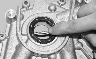
3. Remove the front crankshaft oil seal from the housing bore using any pointed tool (e.g. a screwdriver).
4. Unscrew the pressure relief valve plug from the oil pump housing.
5. Remove the spring and plunger of the pressure reducing valve from the housing cavity.
Warning! The pressure reducing valve spring is installed with tension. To avoid injury, unscrew the plug carefully.
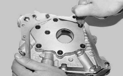
6. Remove the screws securing the pump cover…
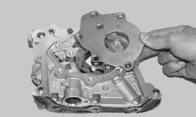
7. …and remove the lid.
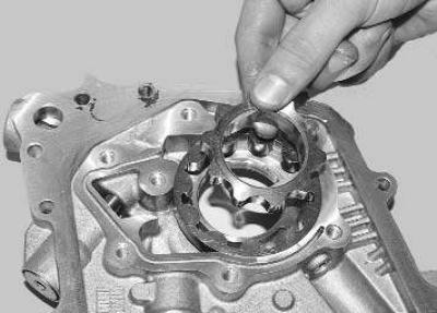
8. Remove the leading… from the housing cavity
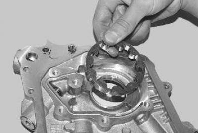
9. …and the driven gear of the pump.
10. Wash the pump body and removed parts to remove dirt and deposits. Remove dense varnish deposits from the internal cavities of the pump, having softened them with a solvent beforehand.
Note: Varnish oil deposits are easily removed with commercially available engine flush products (so-called "five-minute" products).
11. Inspect the pump body and cover. If there are cracks, scratches, casting defects, damaged threaded holes, replace the body (as it cannot be repaired) or the pump assembly.
12. Check the relief valve plunger for scratches and signs of seizure. Small dents and burrs can be removed with a fine-grained sanding stone.
13. Check the pressure reducing valve spring for residual deformation and bending. Replace a spring that is heavily compressed or damaged.
14. Check the gears for metal chipping, scoring and tooth wear. Replace damaged gears or gears that show visually increased one-sided tooth wear.
15. Check the axial clearance between the ends of the gears and the plane of the pump cover. This can be done in the following two ways.
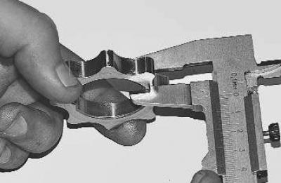
16. In the first method, measure the thickness of the leading…
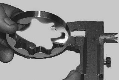
17. …and the driven gear…
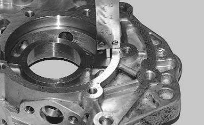
18. …and also the depth of the bore in the housing for the gears. Calculate the axial clearance as the difference between the arithmetic mean of the bore depth and the thickness of the gears.
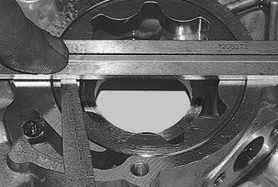
19. For the second method of checking, install the driven gear in the housing, place a metal ruler (or caliper) with the end on the housing and measure the gap between the housing and the ruler with a feeler gauge.
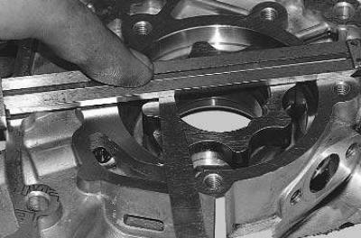
20. Measure the axial clearance of the drive gear in the same way.
21. The maximum allowable clearances measured by both methods should be 0.045–0.100 mm for the driven gear and 0.035–0.085 mm for the driving gear. If at least one of the clearances does not correspond to the specified value, replace the housing or the pump assembly.
22. Assemble the pump in the reverse order of disassembly. Before pressing it into the pump cover, lubricate the front crankshaft oil seal with engine oil. Apply anaerobic thread lock to the threads of the pressure relief valve plug and tighten the plug.
The original article can be viewed on the portal (FordBook.ru)