When cleaning the sealing surfaces, do not use sharp objects to avoid damaging the aluminum parts. Assembly is carried out in the following order:
- Insert the bearing shells and pressure plates into the cylinder block, lubricate the bearings well and place the crankshaft on them. The lubrication holes in the bearings and in the cylinder head must be in line. Rotate the shaft several times so that the liners are well installed;
- Lay three regular liners and one loose leaf with a flange over the crankshaft main journals. The liners should lie well on the necks;
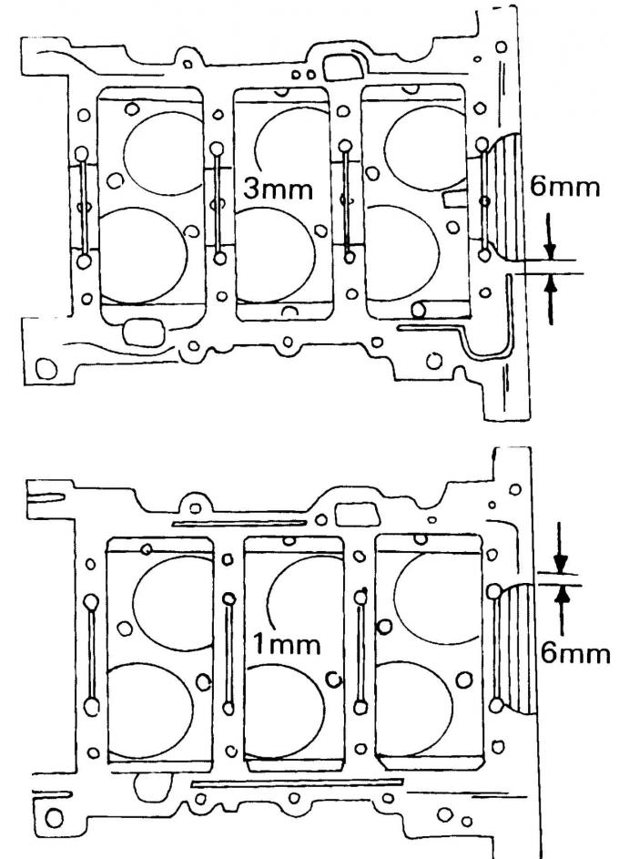
Pic. 332. Sealing places
- Clean both halves of the crankcase. Apply sealant to the surfaces of the cylinder block. It is applied to the separating surfaces in the places shown in Fig. 332. Pay particular attention to the indicated dimensions;
Note: The lower part of the crankcase must be mounted within 4 minutes after applying the sealant.
- check that all the adjusting pins are in the lower part of the crankcase and install the crankcase. Press down on the crankshaft and place half of the pressure plate. Wrap the screws, they should not be lubricated;
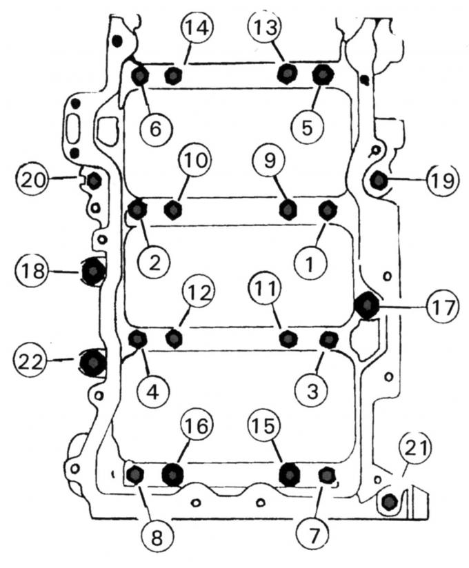
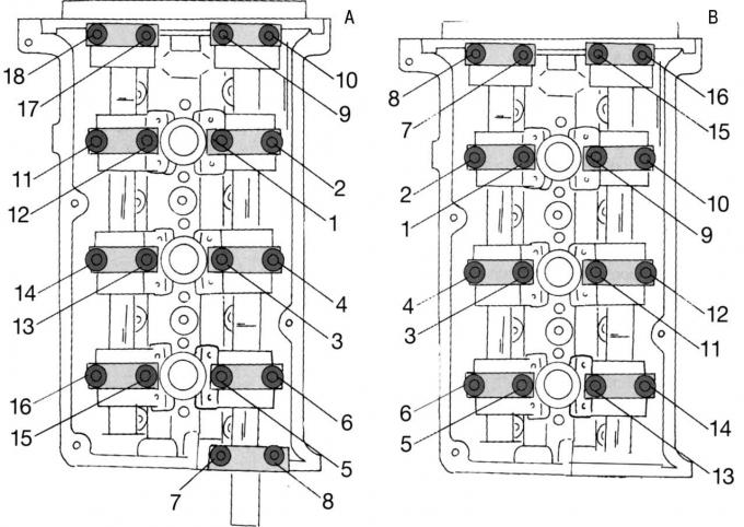
Pic. 333. The sequence of tightening the screws of the lower part of the crankcase
- tighten all screws in the one indicated in fig. 333 sequence tightening torque 4 Nm. Screws 1 to 16 must always be replaced. The tightening of individual screws is carried out in 4 steps:
1st stage - screws 1–8 with a torque of 25 Nm;
2nd stage - screws 9–16 with a torque of 40 Nm;
3rd stage - tighten screws 1–16 a quarter of a turn (90°);
4th stage - screws 17–22 with a torque of 25 Nm;
- after tightening all the screws, turn the crankshaft several times to identify the pinch points. To rotate, screw a screw into the front of the crankshaft or two screws into the rear flange of the shaft and turn the shaft with the screwdriver inserted;
- remove all squeezed out sealant and turn the shaft so that the neck of the installed piston is at BDC;
- install the pistons in the same way as for the 16-valve engine. The arrow on the piston crown must point towards the front of the engine; the notches and grooves of the connecting rod bearing cap must be on the same side; The connecting rod bearing cap screws should always be replaced. The lid is tightened in 3 stages:
1st stage - 23 Nm;
2nd stage - 43 Nm.
Step 3 - Tighten a quarter of a turn (90°);
- after installing all the connecting rods and pistons, check the axial clearance of the connecting rod bearings on the connecting rod journals of the crankshaft (see installation of pistons 16-valve engine). In addition, all the checks mentioned in the same section should be carried out before the installation of the pistons is completed. Then the crankshaft should be rotated again to fix the clamping mechanism;
- Install the oil pump. When tightening the screws, when looking at the pump, first tighten the bottom screw on the right, then the top screw on the right, the bottom screw on the left, and the top screw on the left. All screws are tightened with a torque of 10 Nm;
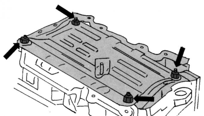
Pic. 334. Fastening the lubrication plate to the open crankcase
- install the oil plate (pic. 334). First tighten the screws with a torque of 5 Nm, and then tighten by another 45° (eighth of the turnover);
- fasten the oil pump intake mesh together with the inlet pipe in two places on the flange and in one place in the middle. Lubricate the new sealing ring with oil before installation. Screw in the screws with a torque of 10 Nm;
- install the oil separator with a new gasket and tighten the screws with a torque of 10 Nm;
- install the console for mounting the hydraulic steering pump and tighten the screws with a torque of 47 Nm. Provide the console with adjustment pins;
- put a new lining of the block of cylinders and establish the block of cylinders. Screw in the screws with washers one by one and tighten firmly. Both cylinder heads are installed in the same way. The tightening of all screws is carried out in several stages:
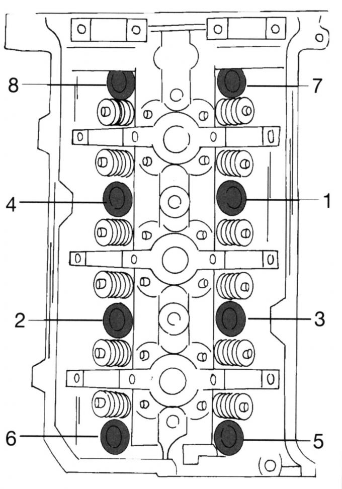
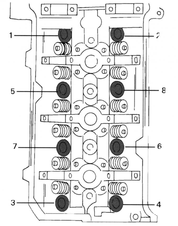
Pic. 335. The sequence of tightening the screws of the cylinder head (both heads)
1st stage - in the indicated in Fig. 335 sequence torque 40 Nm;
2nd stage - in the indicated in Fig. 335 sequences are tightened without the use of a torque wrench by a quarter turn;
Pic. 329. The sequence of unscrewing the screws of the cylinder heads. Both heads turn the same
3rd stage - in the indicated in Fig. 329 sequences are loosened by one turn;
4th stage - in the indicated in Fig. 335 sequence torque 40 Nm;
5th stage - in the indicated in Fig. 335 sequences are tightened without the use of a torque wrench by another quarter turn (90°);
6th stage - in the indicated in Fig. 335 sequences are tightened without the use of a torque wrench again by a quarter turn (90°);
- to mount the left drive chain, set the crankshaft to the desired position. To do this, screw the shock absorber screw with washer into the crankshaft and turn the shaft to the right until the segment key is approximately in position «11 o'clock»;
- insert well-lubricated valve lifters into the appropriate holes;
- lay both camshafts in the left cylinder head and align the marks of the drive gears with the upper edge of the cylinder head:
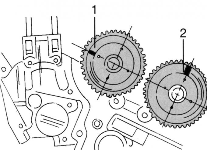
Pic. 336. Installation of camshafts in the left cylinder head: 1 - control mark of the intake camshaft; 2 — an adjusting label of a final camshaft
1) adjusting mark 1 (pic. 336) set the intake camshaft to position «9 o'clock»;
2) adjusting mark 2 of the final camshaft set to position «12 hours»;
- Establish covers of bearings of the left camshafts according to designation of covers. Covers are labeled from «1L» before «9L». Lid «1L» located on the side with four bearing caps on the drive gear side, the cap «5L» located on the other side near the drive gear. Lubricate the surfaces of the lids well. Install covers first «1L» And «5L». The screws are not tightened;
- Place both camshafts in the right cylinder block and turn until the timing marks on the drive gears are aligned with the top edge of the cylinder head. This is done similarly to Fig. 336, but note the following differences:
1) turn the lower shaft (exhaust camshaft) so that the adjusting mark is set to the position «12 hours»;
2) turn the top shaft (intake camshaft) so that the adjusting mark is set to the position «3 hours»;
Note: With four camshafts and two cylinder heads, assembly errors can be easy. For this reason, we recommend that after installing and aligning the adjustment marks, a comprehensive check be carried out again.
- Establish covers of bearings of the right camshafts according to designation of covers. These lids are labeled with «1R» before «8R». Lid «5R» located on the top right next to the drive gear. Behind it are covers from «6R» before «8R». Lid «5R» located on the opposite side next to the drive gear. Behind it are covers from «2R» before «4R». Install covers first «1R» And «5R». The screws are not tightened at this stage;
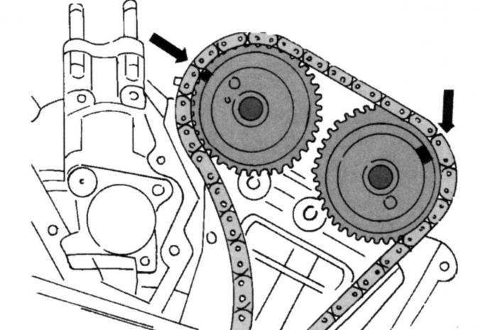
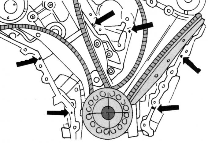
Pic. 337. The location of the alignment marks of the drive gears of the camshafts and copper-colored chain links (left chain)
- Establish the left chain of a drive of camshafts. This chain has copper-colored links that must be aligned with the timing marks on both camshaft drive gears and the crankshaft drive gear. Slide the crankshaft drive gear onto the shaft (alignment mark outside) and install the chain. Install the guide rail located on the right side (black material) and tighten with a torque of 25 Nm. On fig. 337 shows a chain lying on the gears of the camshafts, which also applies to the right camshafts. After installation, check the following again:
1) both links of the copper-colored chain must be located exactly opposite both alignment marks of the camshaft drive gears;
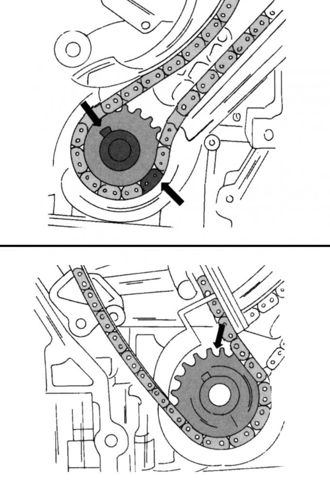
Pic. 338. Crankshaft drive gear and copper-colored link of the left chain (A). In the right chain, the alignment mark is located on the reverse side (IN)
2) the copper colored link on the reverse side must match the timing mark of the crankshaft drive gear (pic. 338, A);
- install the chain clamp on the other side, mount the tensioner still under pretension and tighten with a torque of 25 Nm, then press the clamp firmly against the chain. Hold the bar in this position and remove the locking pin from the tensioner. Now the tensioner is pressed against the clamping bar and provides the required chain tension;
- mount the drive chain on the right side as described above. The guide bar for this chain is light in color. Re-align all alignment marks with the copper colored links. In doing so, pay attention to Fig. 338, B, since these marks are placed in different places. Looking at the chain, screw the guide bar on the right side with a torque of 25 Nm. The installation of the clamping bar and tensioner is carried out in the same way and has already been described above;
- check again that the segment key on the crankshaft is in position «11 o'clock» and insert the pushrods into the left cylinder head;
Pic. 339. The sequence of tightening the screws of the camshaft bearing caps: A - for the left cylinder head; B - for the right cylinder head
- tighten the screws of the camshaft bearing caps (pic. 339) tightening torque 10 Nm;
- turn the crankshaft in the manner described above so that the segment key is in position «3 hours»;
- Lubricate the pushers and insert into the right cylinder head;
- tighten screws of covers of bearings of the right camshafts in specified on the right fig. 339 sequences with a torque of 10 Nm;
Pic. 340. Places for applying sealant
- Install the impulse ring on the crankshaft with a blue mark in the groove and in the places indicated in fig. 340, apply sealant (6 mm wide). The cover of the crankcase of the steering mechanism after its application must be screwed within 6 minutes;
- install new sealing rings for the cover of the crankcase of the steering mechanism and screw it evenly along the circumference with a torque of 25 Nm;
- install the crankshaft position sensor with a new sealing ring (10 Nm) and install the cable clamp;
- Establish a forward sealing ring of a cranked shaft;
- install the crankshaft pulley, hold the shaft, and screw in the screws in four steps:
1st stage - 120 Nm;
2nd stage - loosen the screw one full turn;
3rd stage - 50 Nm;
4th stage - tighten by 90°;
- Mount the hydraulic steering pump with the holder and tighten the screws with a torque of 25 Nm. Then screw in the pin screws with a torque of 10 Nm, first tighten the long pins;
- Install the belt pulley of the hydraulic steering pump and tighten the screws with a torque of 25 Nm;
- lay a new sealing ring and install the rear camshaft ring holder with adjusting pins on the cylinder block. Tighten the screws to 10 Nm. Insert the camshaft O-ring as described above. The same subsection describes the process of mounting the belt pulley on the camshaft;
- Screw in the spark plugs and tighten to 15 Nm;
- Mount covers of heads of the block of cylinders, as it is described above in the corresponding subsection;
- mount the oil pan as described in the relevant subsection and screw on the heat-shielding metal sheet (10 Nm);
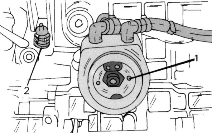
Pic. 341. Installed oil cooler (1) and switch (2) with hydraulic drive
Lubricate the oil cooler O-ring, O-ring and oil filter O-ring with engine oil and install the oil cooler. Fastening in the middle tighten the moment of 57 Н·м. Grease switch 2 (pic. 341) with hydraulic sealant and screw next to the oil cooler 1 (14 Nm). After installing the radiator, you can install an oil filter;
- screw the left exhaust manifold with the converter and a new sealing ring (20 Nm);
- install the generator suspension bracket (25 Nm) and install the generator. Screw the lower screws with a torque of 47 Nm, the upper ones - 25 Nm;
- Establish a back oil-sealing ring of a cranked shaft, as it is described above in the corresponding subsection;
- lay an intermediate plate of the engine and establish a flywheel. Lubricate the screws with sealant and, with the flywheel fixed, evenly, crosswise screw them with a torque of 80 Nm;
- install the liquid pump. Tighten the screws evenly to a torque of 10 Nm and in the final position tighten a further quarter of a turn. Connect the cooling system hoses to the pump;
- Install the coolant connecting pipe with new O-rings between the two cylinder heads. Lubricate them. Screw the screws with a torque of 10 Nm;
- Install the fluid pump drive belt. To do this, turn the tensioner to the right, lay the belt with the pulley and release the tensioner;
- screw the lifting eye of the engine (12 Nm), screw in the dipstick guide tube with a new, oiled O-ring (10 Nm) and install the coolant distribution pipe (10 Nm);
- Establish the case of the thermostat with a hose of a cooling liquid;
- Establish the bottom part of an inlet collector with new linings. The guide grooves of the gaskets must point downwards. From the middle to the edges evenly tighten the screws with a torque of 10 Nm;
- install all cable connectors (connect the plugs) and secure the wires with appropriate clamps;
- Establish the top part of an inlet collector, as it is described earlier in the corresponding subsection. Use new gaskets. They should also point downwards.
Carry out all other work in the reverse order of removal.
Visitor comments