- drain the engine oil;
- Disconnect the EGR wire from the EGR valve. To do this, disconnect the hose and unscrew the wire;
- Turn away the right final collector and remove a lining;
- Turn away a basic plate of a forward power shaft;
- disconnect the following connectors and remove the following wiring harnesses - three-phase current generator wire related to the AGR system, the corresponding connector, the electronic low pressure regulator plug, the plug from the temperature sensor on the coolant distribution pipe. Loosen the two screws and unscrew the wire shaft (two screws);
- hang the wire from the control unit from the holder and then disconnect. Disconnect the plug and unscrew the screws of the intake manifold control unit;
- disconnect all spark plug plugs according to the designation used from the corresponding spark plugs, dismantle the ignition coil together with the ignition cables and connectors. To do this, disconnect the ignition coil plug, disconnect the wire to ground, dismantle the capacitor, unscrew the screws and remove the ignition coil;
- disconnect the low pressure hoses: one from the upper intake manifold, one from the electronic low pressure regulator, one from the fuel pressure regulator and two from the other already disconnected hoses;
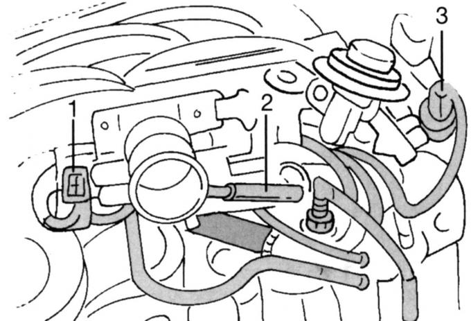
Pic. 321. Detachable hoses and connectors: 1 - throttle angle sensor connector; 2 - crankcase ventilation hose; 3 - idle valve connector
- disconnect connector 1 (pic. 321) throttle angle sensor, crankcase ventilation hose 2, idle valve connector 3;
- Unscrew the upper part of the intake manifold, as described in the relevant section;
- disconnect the connector from the hydraulic switch, camshaft position sensor, crankshaft position sensor and release the wires from the fastener;
- Disconnect the injection cable harness. To do this, disconnect the connectors, including the valve injector connector;
- Remove the thermostat case with a coolant hose;
- Turn off the distributive pipeline of a cooling liquid (two screws on the bottom), unscrew the left bracket for removing or installing the engine and remove the oil dipstick;
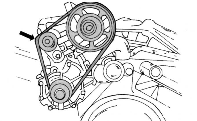
Pic. 322. Removing the fluid pump drive belt
- remove the fluid pump drive belt (pic. 322);
- Remove a hose and the adjusting valve of ventilation of a cranked shaft. To do this, unscrew the nut and remove the hose with the valve;
- Remove the connecting pipeline of a cooling liquid;
- unscrew the screws of the liquid pump and then disconnect the hose connected to the oil cooler;
- hold the flywheel properly and unscrew the screws. Then you can remove the intermediate plate located behind it;
- Remove a back sealing ring of a cranked shaft. Do not damage the crankshaft while doing this;
- Remove the generator and suspension console;
- remove the oil filter, the left intake manifold and unscrew the oil cooler located behind it (loosen the nut in the middle, take out the oil cooler). Now you can unscrew the hydraulic switch located on the left;
- remove the oil pan as described above (at the same time, take into account the sequence of unscrewing and tightening the screws);
- turn away screws of fastening of wires and remove fastening;
- Turn away one screw and remove the right bracket for removal and installation of the engine;
- Remove both covers of a head of the block of cylinders, as it is described above. The same applies to the removal of the belt pulley on the camshaft (see sect. «Replacement of a sealing ring of a camshaft»). Now you can dismantle the oil-tight camshaft ring;
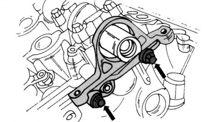
Pic. 323. Fastening of a support of a sealing ring of a camshaft
- unscrew the two screws (pic. 323) and remove the O-ring support. At the same time, try not to damage the camshaft;
- unscrew the belt pulley of the hydraulic steering pump (four screws) and then unscrew the pump together with the console;
- Unscrew the crankshaft pulley together with the vibration damper. In this case, the crankshaft must be secured against rotation. The screw cannot be reused. To remove the absorber, you must have an appropriate puller;
- Remove the sensor and holders of wires;
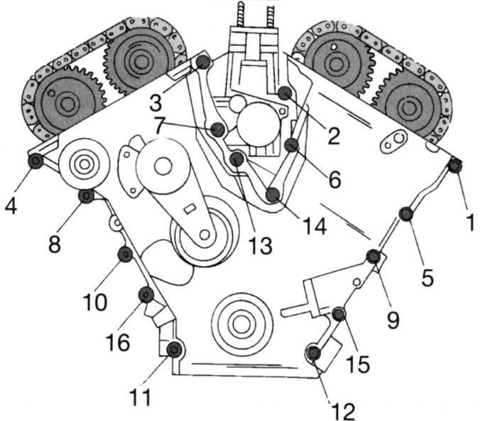
Pic. 324. The sequence of unscrewing the screws on the cover of the timing mechanism
- Turn away a cover of the distributive mechanism from the forward party of the engine. In this case, a certain order of unscrewing the screws must be observed (pic. 324). Remove the pads. Now you can carefully remove the sealing ring from the hole;
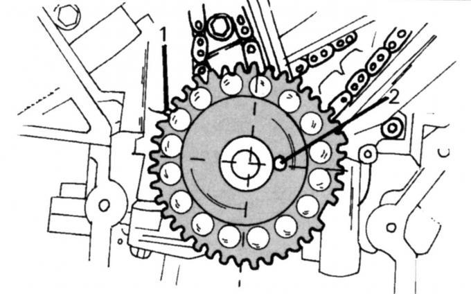
Pic. 325. The position of the crankshaft: 1 - impulse ring; 2 - disc spring
- install the crankshaft in the correct position for subsequent disassembly (pic. 325);
- Unscrew the right chain tensioner and the right camshaft drive chain guide. Then install the tensioner in a vise (with metal jaws), clamp the jaws and push the plunger inward until the pin can be inserted into the hole in the clamp. After being released from the vice, the tensioner is fixed and can no longer be disassembled into parts;
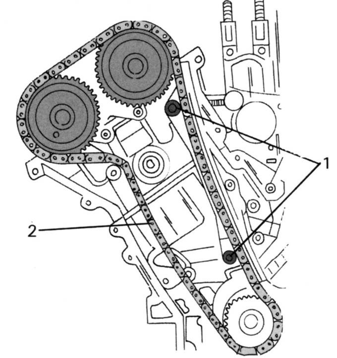
Pic. 326. Laying diagram of the right camshaft drive chain: 1 - screws of the guide bar; 2 - camshaft drive chain
- mark with a felt-tip pen the front side of the drive gear of the right camshaft drive chain, unscrew the screws 1 on the right side (pic. 326) guide plate and remove the drive chain 2 together with the crankshaft drive gear;
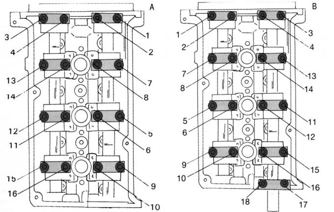
Pic. 327. The sequence of unscrewing the screws to remove the camshaft bearing caps on the left cylinder head (A) and right cylinder head (IN)
- Remove both camshafts of the right cylinder head. To do this, first loosen both bearing housing covers No. 1 and No. 5. Then unscrew all other screws only after the indicated covers have been removed. Then unscrew the screws of the remaining covers as shown in fig. 327 sequences. Now you can remove the camshafts, tappets and valve lifters;
- screw the screw into the front end of the crankshaft and turn to the right until the segment key is in position «11 o'clock». Then turn out this screw;
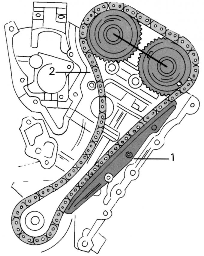
Pic. 328. Scheme of laying the left camshaft drive circuit: 1 - screws of the guide plate; 2 - camshaft drive chain
- Remove the left chain of a drive of camshafts. Mark the front side of the drive gear with a felt pen, remove the tensioner and unscrew the left guide bar. Remove screws 1 (pic. 328) the right chain guide bar and remove the drive chain 2 together with the gear;
- Dismantle two camshafts of the left head of the block of cylinders. First loosen both No. 1 and No. 5 bearing caps. Next, remove all other screws after these caps have been removed. Then release the remaining covers as shown in fig. 327, In sequence, note that this head has two additional bearings. Now you can remove the camshafts, tappets and valve lifters;
- Turn out spark plugs from the left head of the block of cylinders;
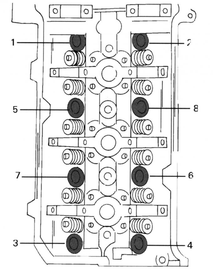
Pic. 329. The sequence of unscrewing the screws of the cylinder heads. Both heads turn the same
- unscrew the screws of the cylinder head (pic. 329) and remove the head. Then remove the gaskets;
- Turn out spark plugs from the right head of the block of cylinders;
- unscrew the screws of the cylinder head (see fig. 329) and remove the head. Then remove the gaskets;
- unscrew the console of the hydraulic drive of the steering, remove the oil separator and remove the gasket;
- Install the cylinder block on the surface of the heads and unscrew the oil pump inlet pipe from the rear side of the crankcase. Then dismantle the metal sheet behind it (fasten in corners);
- Unscrew the oil pump from the front wall of the engine. Loosen the two screws on the left first, then both screws on the right;
- turn the crankshaft (screw the screw into the shaft) until all pistons are about halfway through their stroke, and using a scraper, carefully scrape off the carbon rings from the top of the cylinder bores, being careful not to damage them;
- Unscrew the connecting rod bearing caps one by one. After that, lightly tap the cover with a rubber mallet and remove the cover together with the bearing shell. Usually caps and connecting rods are marked with numbers, be sure to make sure that these marks are visible. The cylinder number is marked respectively on the connecting rod and bearing cap in opposite places. Small rubber elements must be placed on the freely lying pin screws of the connecting rod so that the cylinder mirrors are not damaged during the installation of the pistons;
- Get pistons with rods from the back side through cylinders. The corresponding piston must be at TDC to facilitate removal. It is best to screw the bearing caps and bushings into the respective connecting rods so that they are together. Remove all pistons in the above sequence;
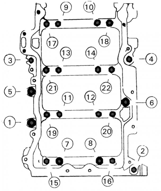
Pic. 330. The sequence of unscrewing the screws of the lower part of the crankcase
- unscrew the lower part of the crankcase (pic. 330). Screws 7-22 are malleable screws that should always be replaced. Raise part of the body. If necessary, help with a rubber mallet;
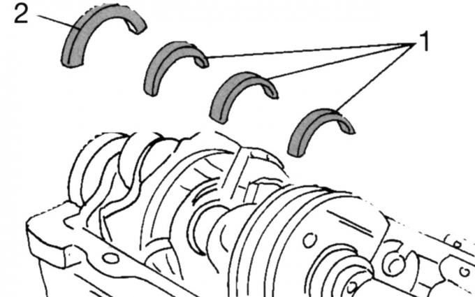
Pic. 331. Inserts of bearings of a cranked shaft: 1 — usual loose leaves; 2 - insert with flange
- Remove the bottom loose leaves of radical bearings. Three earbuds 1 (pic. 331) are identical, and one liner 2 has a clamping flange to compensate for the axial clearance of the crankshaft. Each insert is properly labeled (e.g. color stroke), so that they can be installed in their original position;
- carefully take out a cranked shaft from bearings and put on a pure place;
- remove the bearing shells located in the crankcase, mark them accordingly so as not to confuse them, and put them to the other shells. Remove the thrust pressure plate from the crankcase side.
Visitor comments