|
STATES |
DETAILS/RESULTS/ACTIONS |
|
A1: CHECKING THE OPERATION OF THE SOUND SIGNAL |
|
|
1Press the horn switches. |
|
|
• Does the signal sound? |
|
|
→ Yes |
|
|
Go to A2 |
|
|
→ No |
|
|
Perform airbag sliding contact diagnostics. Refer to Section 413-06 for additional information. |
|
|
A2: CHECKING THE SWITCH OPERATION |
|
|
1Disconnect the Speed Control System Actuator - C831. |
|
|
2Disconnect the Airbag Sliding Contact - C896. |
|
|
3Remove fuse 53 (10 A). |
|
|
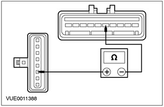
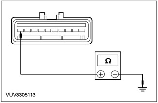
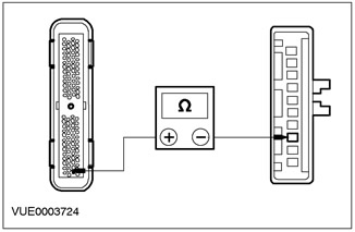
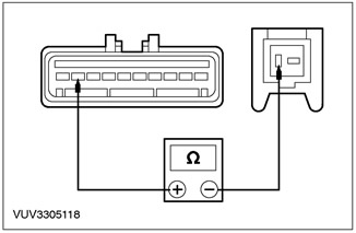
4Using a digital multimeter, measure the resistance between pin 5 of the speed control actuator C831, circuit 8-PG13 (white), harness side, and pin 6 of the air bag wiper C896, circuit 15-PG13 (white), harness side, with the ON switch pressed. |
|
• Is the resistance between 260 and 280 ohms? |
|
|
→ Yes |
|
|
Install fuse 53 (10A). Go to A3 |
|
|
→ No |
|
|
Install fuse 53 (10A). Go to A5 |
|
|
A3: CHECKING THE SWITCH INPUT SIGNAL TO THE SPEED CONTROL SYSTEM ACTUATOR |
|
|
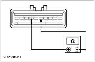
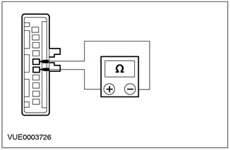
1Using a digital multimeter, measure the resistance between pin 5 of the speed control actuator C831, circuit 8-PG13 (white), harness side, and pin 6 of the speed control actuator C831, circuit 9-PG13 (brown), harness side, with the OFF switch pressed. |
|
• Is the resistance less than 5 ohms? |
|
|
→ Yes |
|
|
Go to A6 |
|
|
→ No |
|
|
Go to A4 |
|
|
A4: CHECK THE ELECTRICAL CIRCUIT 8-PG13 (WHITE) FOR OPENINGS. |
|
|
WARNING: For additional information, refer to Section 501-20A / 501-20B for the proper procedure for disabling the air bag system. |
|
|
1Disconnect the airbag sliding contact. |
|
|
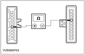
2Using a digital multimeter, measure the resistance between pin 5 of the speed control actuator C831, circuit 8-PG13 (white), wiring harness side, and pin 4 of the air bag wiper C896, circuit 8-PG13 (white), wiring harness side. |
|
• Is the resistance less than 5 ohms? |
|
|
→ Yes |
|
|
Go to A5 |
|
|
→ No |
|
|
Repair electrical circuit 8-PG13 (white). Check the correct operation of the system. |
|
|
A5: CHECK THE AIR BAG SLIDING CONTACT CIRCUIT FOR OPENINGS |
|
|
1Disconnect the Speed Control Switch - C921. |
|
|
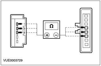
2Using a digital multimeter, measure the resistance between pin 4 (white) of the air bag slider connector C896, slider side, and pin 3 of the air bag slider connector C921, slider side, and between pin 5 (brown) of the air bag slider connector C896, slider side, and pin 2 of the air bag slider connector C921, slider side, and between pin 6 (green/yellow) of the air bag slider connector C896, slider side, and between pin 1 of the air bag slider connector C921, component side. |
|
• Is the resistance less than 5 ohms? |
|
|
→ Yes |
|
|
Install a new speed control switch. Check that the system operates correctly. |
|
|
→ No |
|
|
Install a new airbag sliding contact. Check that the system is operating correctly. |
|
|
A6: CHECK ELECTRICAL CIRCUIT 91-PG12 (BLACK/WHITE) FOR OPEN |
|
|
1Using a digital multimeter, measure the resistance between pin 10 C831 of the speed control actuator, circuit 91-PG12 (black/white), harness side, and ground. |
|
• Is the resistance less than 5 ohms? |
|
|
→ Yes |
|
|
Go to A7 |
|
|
→ No |
|
|
Repair the electrical circuit. Check the correct operation of the system. |
|
|
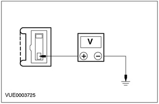
A7: CHECKING ELECTRICAL CIRCUIT 15-PG12 (GREEN/WHITE) FOR VOLTAGE |
|
|
1Enter the ON position. |
|
|
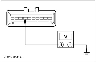
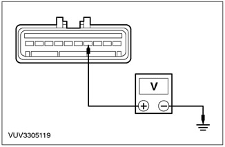
2Using a digital multimeter, measure the voltage between pin 7 of the speed control actuator C831, circuit 15-PG12 (green/white), harness side, and ground. |
|
• Is the resistance more than 10V? |
|
|
→ Yes |
|
|
Go to A8 |
|
|
→ No |
|
|
Check fuse 53 (10A). If it is blown, install a new fuse. Check for proper system operation. If the fuse blows again, check for a short to ground. If the fuse is good, repair circuit 15-PG12 (green/white). Check for proper system operation. |
|
|
A8: CHECKING THE BRAKE PEDAL POSITION SWITCH (BPPS) INPUT |
|
|
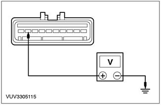
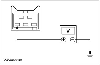
1Using a digital multimeter, measure the voltage between pin 9 of the speed control actuator C831, circuit 15S-PG16 (green/yellow), harness side, and ground. |
|
• Is the resistance more than 10V? |
|
|
→ Yes |
|
|
Go to A12 |
|
|
→ No |
|
|
Go to A9 |
|
|
A9: CHECKING THE BRAKE PEDAL POSITION SWITCH (BPPS) |
|
|
1Disconnect the BPP Switch - C824. |
|
|
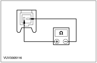
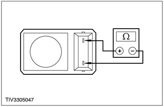
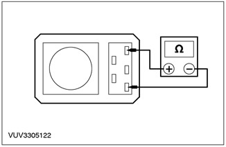
2Using a digital multimeter, measure the resistance between pins 1 and 2 of the C824 BPP switch, on the switch side, with the switch plunger pressed and released. |
|
• Is the resistance greater than 10,000 ohms with the plunger depressed and less than 5 ohms with the plunger released? |
|
|
→ Yes |
|
|
Go to A10 |
|
|
→ No |
|
|
Install a new BPP switch. Check that the system is working properly. |
|
|
A10: CHECK ELECTRICAL CIRCUIT 15-PG6 (GREEN/YELLOW) FOR VOLTAGE IN THE CIRCUIT |
|

|
1Using a digital multimeter, measure the voltage between pin 2 of the BPP switch, C824, circuit 15-PG6 (green/yellow), harness side, and ground. |
|
• Is the resistance more than 10V? |
|
|
→ Yes |
|
|
Go to A11 |
|
|
→ No |
|
|
Check fuse 54 (15A). If it is blown, install a new fuse. Check for proper system operation. If the fuse blows again, check for a short to ground. If the fuse is good, repair circuit 15-PG6 (green/yellow). Check for proper system operation. |
|
|
A11: CHECK ELECTRICAL CIRCUIT 15S-PG16 (GREEN/YELLOW) FOR OPEN |
|

|
1Using a digital multimeter, measure the resistance between pin 9 of the speed control actuator C831, circuit 15S-PG16 (green/yellow), harness side, and pin 1 of the BPP switch C824, circuit 15S-PG16 (green/yellow), harness side. |
|
• Is the resistance less than 5 ohms? |
|
|
→ Yes |
|
|
Adjust the BPP switch. Check that the system is working properly. |
|
|
→ No |
|
|
Repair electrical circuit 15S-PG16 (green/yellow). Check that the system operates correctly. |
|
|
A12: CHECKING THE SIGNAL FROM THE STOP LIGHT SWITCH TO THE ACTUATOR |
|
|
1Using a digital multimeter, measure the voltage between pin 4 of the speed control actuator C831, circuit 15S-PG17 (green/blue), harness side, and ground with the brake pedal depressed. |
|
• Is the resistance more than 10V? |
|
|
→ Yes |
|
|
Go to A15 |
|
|
→ No |
|
|
Vehicles with manual transmission in the block with the driving axle. Go to A13 If the brake lights are functioning properly, REPAIR the 15S-PG17 (Green/Blue) circuit. Check for proper system operation. |
|
|
If the brake lights are not functioning, refer to Section 417-01 for additional information. |
|
|
A13: CHECK POWER SUPPLY TO CLUTCH PEDAL POSITION SWITCH (CPP). |
|
|
1Disconnect the CPP Switch - C825. |
|
|
2Using a digital multimeter, measure the voltage between pin 3 of the CPP switch, C825, circuit 15S-PG7 (green/blue), harness side, and ground, with the clutch pedal depressed. |
|
• Is the resistance more than 10V? |
|
|
→ Yes |
|
|
Go to A14 |
|
|
→ No |
|
|
Repair electrical circuit 15S-PG7 (green/blue). Check that the system is operating correctly. |
|
|
A14: CHECKING THE CLUTCH PEDAL POSITION SWITCH (CPP) |
|

|
1Using a digital multimeter, measure the resistance between pins 1 and 3 of the C825 CPP switch, on the switch side. |
|
• Is the resistance less than 5 ohms? |
|
|
→ Yes |
|
|
Repair electrical circuit 15S-PG7 (green/blue). Check that the system is operating correctly. |
|
|
→ No |
|
|
Adjust or install a new CPP switch. Check that the system is operating correctly. |
|
|
A15: CHECKING THE SIGNAL FROM THE VEHICLE SPEED SENSOR (VSS) TO THE ACTUATOR |
|
|
1Disconnect the Instrument Cluster - C809. |
|
|
2Disconnect the Powertrain Control Module (PCM) - C415. |
|
|
3Using a digital multimeter, measure the resistance between pin 28 of the C415 PCM (pin 4 on the 60-pin PCM), circuit 8-RE22 (White/Green), harness side, and pin 3 of the C831 Speed Control Actuator, circuit 8-PG18 (White/Blue), harness side. |
|
• Is the resistance greater than 10,000 ohms? |
|
|
→ Yes |
|
|
Repair electrical circuit 8-PG18 (white/blue) or 8-RE22 (white/green). Check that the system is operating correctly. |
|
|
→ No |
|
|
Use WDS/FDS 2000 to retrieve stored DTCs. If DTCs are not present, install a new speed control actuator. Check that the system is operating correctly. |
|
PINPOINT TEST B: THE SPEED CONTROL SYSTEM DOES NOT DISCONNECT WHEN THE BRAKE PEDAL IS APPLIED
|
STATES |
DETAILS/RESULTS/ACTIONS |
|
B1: CHECKING THE BRAKE PEDAL POSITION SWITCH (BPPS) |
|
|
1Enter the OFF position. |
|
|
2Disconnect the BPP Switch - C824. |
|
|
3Using a digital multimeter, measure the resistance between pins 1 and 2 of the C824 BPP switch, on the switch side, with the brakes not applied. |
|
• Is the resistance less than 5 ohms? |
|
|
→ Yes |
|
|
Go to B2 |
|
|
→ No |
|
|
Adjust or install a new BPP switch. Check that the system is working properly. |
|
|
B2: CHECK ELECTRICAL CIRCUIT 15-PG6 (GREEN/YELLOW) OF BRAKE PEDAL POSITION SWITCH FOR VOLTAGE |
|
|
1Enter the ON position. |
|
|
2Using a digital multimeter, measure the voltage between pin 2 of the BPP switch, C824, circuit 15-PG6 (green/yellow), harness side, and ground. |
|
• Is the resistance more than 10V? |
|
|
→ Yes |
|
|
Go to B3 |
|
|
→ No |
|
|
If the brake lights are working, repair the 15-PG6 (green/yellow) circuit. Check for proper system operation. |
|
|
If the brake lights do not work, refer to Section 417-01 for additional information. |
|
|
B3: CHECKING ELECTRICAL CIRCUIT 15S-PG16 (GREEN/YELLOW) FOR OPEN |
|
|
1Enter the OFF position. |
|
|
2Disconnect the Speed Control System Actuator - C831. |
|
|
3Using a digital multimeter, measure the resistance between pin 1 of the BPP switch C824, circuit 15S-PG16 (green/yellow), and pin 9 of the speed control system C831, circuit 15S-PG16 (green/yellow), on the wiring harness side. |
|
• Is the resistance less than 5 ohms? |
|
|
→ Yes |
|
|
Install a new speed control actuator. Check that the system is operating correctly. |
|
|
→ No |
|
|
Repair electrical circuit 15S-PG16 (green/yellow). Check that the system operates correctly. |
|
PINPOINT TEST C: COAST SWITCH FAULT
|
STATES |
DETAILS/RESULTS/ACTIONS |
|
C1: CHECKING THE COAST SWITCH |
|
|
1Enter the OFF position. |
|
|
2Disconnect the Speed Control System Actuator - C831. |
|

|
3Using a digital multimeter, measure the resistance between pin 5 of the speed control actuator, C831, circuit 8-PG13 (white), and pin 6 of the C831, circuit 9-PG13 (brown), harness side, with the COAST switch pressed. |
|
• Is the resistance between 110 and 130 ohms? |
|
|
→ Yes |
|
|
Install a new speed control actuator. Check that the system is operating correctly. |
|
|
→ No |
|
|
Go to C2 Proceed to PINPOINT TEST C |
|
|
C2: CHECKING THE RESUME SWITCH |
|

|
1Using a digital multimeter, measure the resistance between pin 5 of C831 of the speed control actuator, circuit 8-PG13 (white), and pin 6 of C831 of the circuit 9-PG13 (brown), on the wiring harness side, with the RESUME switch pressed. |
|
• Is the resistance between 110 and 130 ohms? |
|
|
→ Yes |
|
|
Install a new COAST switch. Check that the system is working properly. |
|
|
→ No |
|
|
Go to A4 |
|
PINPOINT TEST D: RESUME SWITCH FAILURE
|
STATES |
DETAILS/RESULTS/ACTIONS |
|
D1: CHECKING THE RESUME SWITCH |
|
|
1Enter the OFF position. |
|
|
2Disconnect the Speed Control System Actuator - C831. |
|
|
3Using a digital multimeter, measure the resistance between pin 5 of C831, speed control actuator, circuit 8-PG13 (white), harness side, and pin 6 of C831, circuit 9-PG13 (brown), harness side, with the RESUME switch pressed. |
|
• Is the resistance between 110 and 130 ohms? |
|
|
→ Yes |
|
|
Install a new speed control actuator. Check that the system is operating correctly. |
|
|
→ No |
|
|
Go to D2. |
|
|
D2: CHECKING THE COAST SWITCH |
|

|
1Using a digital multimeter, measure the resistance between pin 5 of the speed control actuator, C831, circuit 8-PG13 (white), and pin 6 of the C831, circuit 9-PG13 (brown), harness side, with the COAST switch pressed. |
|
• Is the resistance between 110 and 130 ohms? |
|
|
→ Yes |
|
|
Install a new RESUME switch. Check that the system is working properly. |
|
|
→ No |
|
|
Go to A4 |
|
PINPOINT TEST E: THE SPEED CONTROL SYSTEM DOES NOT DISCONNECT WHEN THE CLUTCH PEDAL IS DEPRESSED
|
STATES |
DETAILS/RESULTS/ACTIONS |
|
E1: CHECKING THE CLUTCH PEDAL POSITION SWITCH (CPP) |
|
|
1Disconnect the CPP Switch - C825. |
|
|
2Using a digital multimeter, measure the resistance between pins 1 and 3 of the C825 CPP switch on the switch side, with the switch plunger pressed and released. |
|
• Is the resistance greater than 10,000 ohms with the plunger depressed and less than 5 ohms with the plunger released? |
|
|
→ Yes |
|
|
Adjust the CPP switch. |
|
|
→ No |
|
|
Install a new CPP switch. |
|
For more information, please visit the specified website (fordbook)