|
STATES |
DETAILS/RESULTS/ACTIONS |
|
A1: COMPLAINT VERIFICATION |
|
|
1 Test the operation of the interior lights in the ON positions (incl.) and 12 SEC. |
|
|
• Interior lamp not working in both positions? |
|
|
→ Yes |
|
|
Go to A16 |
|
|
→ No |
|
|
If the lamp does not work in position 12 SEC Go to A2 |
|
|
If the lamp does not work in the ON position, Go to A11 |
|
|
A2: CHECK INPUT SIGNAL FROM INTERIOR LIGHT SWITCHES |
|
|
NOTE: Make sure the front interior lamp switch is set to 12 SEC. |
|
|
1 Check the operation of all door sill lights. |
|
|
• Are the door sill lights not working on just one door? |
|
|
→ Yes |
|
|
If the interior lamp switch in the driver's door does not work, Go to A3 |
|
|
If the interior light switch in any other door does not work, Go to A6 |
|
|
→ No |
|
|
Go to A11 |
|
|
A3: CHECKING THE SIGNAL OF THE INTERIOR LIGHT SWITCH LOCATED IN THE DRIVER'S DOOR SENT TO THE MODULE |
|
|
1 Disconnect the C51 CTM. |
|
|
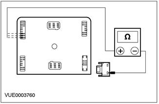
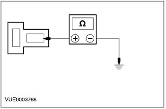
2 Measure the resistance between pin 62 (left hand drive variant) or pin 63 (right hand drive variant) connector C51 CTM, on the element side, and ground. Take readings while pressing (the door is closed) and unpressed (the door is open) interior lamp door switch. |
|
• Resistance less than 5 ohms (the door is open) and more than 10 000 Ohm (the door is closed)? |
|
|
→ Yes |
|
|
INSTALL a new CTM. CHECK the system is working properly. |
|
|
→ No |
|
|
Go to A4 |
|
|
A4: CHECK THE ELECTRICAL CIRCUIT OF THE PIN IN THE DRIVER'S DOOR FOR AN OPEN |
|
|
1 Disconnect Driver's door interior light switch C685 (left hand drive variant), C684 (right hand drive variant). |
|
|
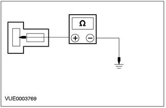
2 Measure the resistance between pin 1 of connector C685 (left hand drive variant) or pin 1 C684 (right hand drive variant) interior lighting lamp switch, from the wiring side, and pin 62 (left hand drive variant) or pin 63 (right hand drive variant) C51 central timer module, wiring side. |
|
• Is the resistance less than 5 ohms? |
|
|
→ Yes |
|
|
Go to A5 |
|
|
→ No |
|
|
REPAIR circuit 31S-GL16 (black and blue) for left-hand drive version Or electric circuit 31S-GL9 (black and yellow) for right hand drive. CHECK the system is working properly. |
|
|
A5: CHECK THE GROUND CIRCUIT OF THE INTERIOR LIGHT SWITCH LOCATED IN THE DRIVER'S DOOR FOR AN OPEN |
|
|
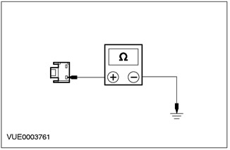
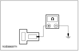
1 Measure the resistance between pin 2 of connector C685, circuit 31-GL9 (black) (left hand drive variant) or pin 2 connector C684, electrical circuit 31-GL16 (black) (right hand drive variant) interior lighting lamp switch, from the wiring side, and ground. |
|
• Is the resistance less than 5 ohms? |
|
|
→ Yes |
|
|
INSTALL a new interior lamp switch in the driver's door. CHECK the system is working properly. |
|
|
→ No |
|
|
REPAIR Circuit 31-GL9 (black) (left hand drive variant) or electrical circuit 31-GL16 (black) (right hand drive variant). CHECK the system is working properly. |
|
|
A6: CHECK THE LIGHT DOOR SWITCH SIGNAL SENT TO THE UNIT |
|
|
1 Disconnect the C51 CTM. |
|
|
2 Measure the resistance between pin 64, wiring side, (rear doors), or pin 62, on the wiring side, (passenger door, right hand drive version), or pin 63, on the wiring side, (passenger door, left-hand drive version), C51 CTM connector and ground. Take readings while pressing (the door is closed) and unpressed (the door is open) interior lamp door switch. |
|
• Is the resistance greater than 10,000 ohms with the switch pressed and less than 5 ohms with the switch not pressed? |
|
|
→ Yes |
|
|
INSTALL the new CTM. CHECK the system is working properly. |
|
|
→ No |
|
|
Go to A7 |
|
|
A7: CHECKING INTERIOR LIGHTING DOOR SWITCH CIRCUIT FOR OPEN |
|
|
1 Disconnect C686, C687, C684 and C685 interior lamp switches. |
|
|
2 Measure the resistance between pin 64 of the C51 CTM connector (rear doors) and pin 1 of connector C687 of the interior light switch (left rear door), or pin 1 of connector C686 of the interior light switch (right rear door). For front passenger door between pin 62 of connector C51CTM (right hand drive variant) or pin 63 (left hand drive variant) and pin 1 of connector C685 (right hand drive variant) or pin 1 of connector C686 (left hand drive variant) interior lamp switch. |
|
• Is the resistance less than 5 ohms? |
|
|
→ Yes |
|
|
Go to A8 |
|
|
→ No |
|
|
REPAIR circuit 31S-GL16 (black and blue) for passenger door (left hand drive variant) or electrical circuit 31S-GL9 (black and yellow) for passenger door (right hand drive variant). For rear doors repair chain 31S-GL19 (black and green) (rear right door), or electrical circuit 31S-GL12 (black and orange) (rear left door). CHECK the system is working properly. |
|
|
A8: INSPECTION OF INTERIOR LIGHT DOOR SWITCH GROUND CIRCUIT FOR OPEN GROUND |
|
|
1 Measure the resistance between pin 1 of connector C684, (passenger door, left-hand drive version) or pin 1 of connector C685 (passenger door, right hand drive version), or pin 1 of connector C686 (right rear door), or pin 1 of connector C687 (left rear door) interior lighting lamp switch, from the wiring side, and ground. |
|
• Is the resistance less than 5 ohms? |
|
|
→ Yes |
|
|
Go to A9 |
|
|
→ No |
|
|
REPAIR Circuit 31-GL9 (black) (right hand drive variant) or electrical circuit 31-GL16 (black) (left hand drive variant). For rear doors REPAIR circuit 31-GL19 (black) (right rear door) or electrical circuit 31-GL12 (black) (left rear door). CHECK the system is working properly. |
|
|
A9: CHECK THE FRONT INTERIOR LIGHT CIRCUIT FOR OPEN |
|
|
1 Disconnect the C899 front interior lamp. |
|
|
2 Disconnect the C890 front interior lamp. |
|
|
3 Set the front interior lamp switch to position 12 SEC. |
|
|
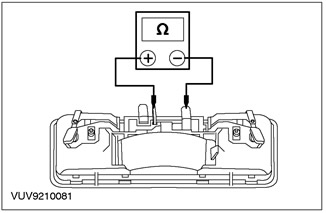
4 Measure the resistance between C899 connector pin 1 of the front interior light and C890 connector pin 1 of the front interior light (element side). |
|
• Is the resistance less than 5 ohms? |
|
|
→ Yes |
|
|
Go to A10 |
|
|
→ No |
|
|
INSTALL a new front interior lamp. CHECK the system is working properly. |
|
|
A10: 31-LC7 GROUND CIRCUIT CHECK (BLACK) FRONT INTERIOR LAMP FOR BREAK |
|
|
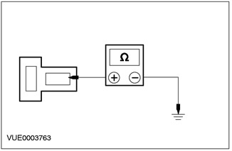
1 Measure the resistance between pin 2 of connector C890, front interior lamp, circuit 31-LC7 (black), from the wiring side, and "ground". |
|
• Is the resistance less than 5 ohms? |
|
|
→ Yes |
|
|
INSTALL a new interior lamp switch. CHECK the system is working properly. |
|
|
→ No |
|
|
REPAIR Circuit 31-LC7 (black). CHECK the system is working properly. |
|
|
A11: 29-LC7 CIRCUIT VOLTAGE CHECK (ORANGE-BLUE) |
|
|
1 Disconnect the C899 front interior lamp. |
|

|
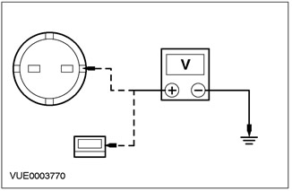
2 Measure the voltage between pin 1 of connector C899, front interior lamp, circuit 29-LC7 (orange-blue), from the wiring side, and "ground". |
|
• Is the voltage greater than 10 V? |
|
|
→ Yes |
|
|
Go to A15 |
|
|
→ No |
|
|
Go to A12 |
|
|
A12: 29-LC7 ELECTRICAL CIRCUIT CHECK (ORANGE-BLUE) FOR GAPS |
|
|
1 Disconnect the battery saver relay. |
|

|
2 Measure the resistance between battery saver relay pin 5 and connector C899 pin 1, circuit 29-LC7 (orange-blue), from the side of the electrical wiring. |
|
• Is the resistance less than 5 ohms? |
|
|
→ Yes |
|
|
Go to A13 |
|
|
→ No |
|
|
REPAIR Circuit 29-LC7 (orange-blue). CHECK the system is working properly. |
|
|
A13: CHECKING THE POWER SUPPLY TO THE BATTERY SAVER RELAY |
|

|
1 Measure the voltage between pin 3 of the battery saver relay, circuit 30-DA1 (red), from the wiring side, and "ground". |
|
• Is the voltage greater than 10 V? |
|
|
→ Yes |
|
|
Go to A14 |
|
|
→ No |
|
|
CHECK fuse 35 (7.5 A) and fuse 7 (40 A). INSTALL a new fuse if necessary (And). If both fuses are good, REPAIR circuit 30-DA1 (red). CHECK the system is working properly. |
|
|
A14: CHECKING THE STATUS OF THE BATTERY SAVER RELAY |
|
|
1 Perform battery saver relay element test. For more information, refer to Checking Elements available in this section.. |
|
|
• Relay OK? |
|
|
→ Yes |
|
|
INSTALL a new CTM. CHECK the system is working properly. |
|
|
→ No |
|
|
INSTALL a new battery saver relay. CHECK the system is working properly. |
|
|
A15: FRONT INTERIOR LIGHT GROUND CIRCUIT CHECK |
|
|
1 Disconnect the C890 front interior lamp. |
|
|
2 Measure the resistance between pin 2 of connector C890, front interior light, circuit 31-LC7 (black), from the wiring side, and "ground". |
|
• Is the resistance less than 5 ohms? |
|
|
→ Yes |
|
|
INSTALL a new front interior lamp. CHECK the system is working properly. |
|
|
→ No |
|
|
REPAIR Circuit 31-LC7 (black). CHECK the system is working properly. |
|
|
A16: CHECKING THE STATUS OF THE FRONT INTERIOR LIGHT LIGHT |
|
|
1 Remove and inspect the front interior light bulb. |
|
|
• Is the front interior lamp bulb OK? |
|
|
→ Yes |
|
|
Go to A17 |
|
|
→ No |
|
|
INSTALL a new front interior lamp bulb. CHECK the system is working properly. |
|
|
A17: 29-LC7 CIRCUIT VOLTAGE CHECK (ORANGE-BLUE) |
|
|
1 Disconnect the C899 front interior lamp. |
|

|
2 Measure the voltage between pin 1 of connector C899, front interior lamp, circuit 29-LC7 (orange-blue), from the wiring side, and "ground". |
|
• Is the voltage greater than 10 V? |
|
|
→ Yes |
|
|
INSTALL a new front interior lamp. CHECK the system is working properly. |
|
|
→ No |
|
|
Go to A18 |
|
|
A18: 29-LC7 ELECTRICAL CIRCUIT CHECK (ORANGE-BLUE) FOR GAPS |
|
|
1 Disconnect the battery saver relay. |
|
2 Measure the resistance between battery saver relay pin 5 and front interior lamp connector C899 pin 1, circuit 29-LC7 (orange-blue), from the wiring side, |
|
|
• Is the resistance less than 5 ohms? |
|
|
→ Yes |
|
|
Go to A19 |
|
|
→ No |
|
|
REPAIR Circuit 29-LC7 (orange-blue). CHECK the system is working properly. |
|
|
A19: CHECKING THE POWER SUPPLY TO THE BATTERY SAVER RELAY |
|
|
1 Measure the voltage between pin 3 of the battery saver relay, circuit 30-DA1 (red), from the wiring side, and "ground". |
|
• Is the voltage greater than 10 V? |
|
|
→ Yes |
|
|
Go to A20 |
|
|
→ No |
|
|
CHECK fuse 35 (7.5 A) and fuse 7 (40 A). INSTALL a new fuse if necessary (And). If both fuses are good, REPAIR circuit 30-DA1 (red). CHECK the system is working properly. |
|
|
A20: CHECKING THE STATUS OF THE BATTERY SAVER RELAY |
|
|
1 Perform battery saver relay element test. For more information, refer to Checking Elements available in this section.. |
|
|
• Relay OK? |
|
|
→ Yes |
|
|
INSTALL a new CTM. CHECK the system is working properly. |
|
|
→ No |
|
|
INSTALL a new battery saver relay. CHECK the system is working properly. |
|
PINPOINT TEST B: REAR INTERIOR LIGHT DOES NOT WORK
|
STATES |
DETAILS/RESULTS/ACTIONS |
|
B1: CHECKING THE FUNCTION OF THE FRONT INTERIOR LIGHT |
|
|
1 Visually check that the front interior lamp is on. |
|
|
• Does the front interior light come on? |
|
|
→ Yes |
|
|
Navigate to B2 |
|
|
→ No |
|
|
Go to A11 |
|
|
B2: CIRCUIT VOLTAGE CHECK 29-LC17 (ORANGE YELLOW) |
|
|
1 Measure the voltage between pin 1 of connector C892, rear interior light, circuit 29-LC17 (orange yellow), from the wiring side, and "ground". |
|
• Is the voltage greater than 10 V? |
|
|
→ Yes |
|
|
Go to B3 |
|
|
→ No |
|
|
REPAIR Circuit 29-LC17 (orange yellow). CHECK the system is working properly. |
|
|
B3: REAR INTERIOR LIGHT ON AND 12 SEC CHECK |
|
|
1 Test the operation of the rear interior lamp in ON and 12 SEC modes. |
|
|
• Both modes do not work? |
|
|
→ Yes |
|
|
CHECK the condition of the bulb. If the bulb is burned out, INSTALL a new bulb. If the bulb is OK, INSTALL a new rear interior lamp. CHECK the system is working properly. |
|
|
→ No |
|
|
If the ON position does not work, Go to B4 |
|
|
If regulation 12 SEC doesn't work, Go to B5 |
|
|
B4: ELECTRICAL CIRCUIT CHECK 31-LC17 (BLACK) FOR GAPS |
|
|
1 Disconnect the C891 rear interior lamp. |
|
|
2 Measure the resistance between pin 2 of connector C891 rear interior lamp circuit 31-LC17 (black), from the wiring side, and "ground". |
|
• Is the resistance less than 5 ohms? |
|
|
→ Yes |
|
|
INSTALL a new rear interior lamp. CHECK the system is working properly. |
|
|
→ No |
|
|
REPAIR Circuit 31-LC17 (black). CHECK the system is working properly. |
|
|
B5: ELECTRICAL CIRCUIT CHECK 31S-LC17 (BLACK YELLOW) FOR GAPS |
|
|
1 Disconnect the C891 rear interior lamp. |
|
|
2 Make sure the door is open. |
|
|
3 Measure the resistance between pin 1 of connector C891 rear interior lamp circuit 31S-LC17 (black and yellow), from the wiring side, and "ground". |
|
• Is the resistance less than 5 ohms? |
|
|
→ Yes |
|
|
INSTALL a new rear interior lamp. CHECK the system is working properly. |
|
|
→ No |
|
|
REPAIR circuit 31S-LC17 (black and yellow). CHECK the system is working properly. |
|
PINPOINT TEST C: CARGO LIGHT DOES NOT WORK
|
STATES |
DETAILS/RESULTS/ACTIONS |
|
C1: 29-LB25 CARGO LIGHT VOLTAGE CHECK (ORANGE-BLUE) OR 29-LB6 (ORANGE YELLOW) |
|
|
1 Enter the OFF position. |
|
2 Disconnect the C820 or C887 luggage compartment lamps ("Universal"). |
|
|
3 Measure the voltage between pin 2 of connector C820 luggage compartment lamp circuit 29-LB25 (orange-blue) (besides "universal"), or pin 1 of connector C887, circuit 29-LB6 (orange yellow) (only "universal"), from the wiring side, and "ground". |
|
|
• Is the voltage greater than 10 V? |
|
|
→ Yes |
|
|
Go to C2 |
|
|
→ No |
|
|
REPAIR Circuit 29-LB25 (orange-blue) (with the exception of "universal"), or electrical circuit 29-LB6 (orange yellow) (only "universal"). CHECK the system is working properly. |
|
|
C2: GROUND CHECK OF CARGO LIGHT |
|
|
NOTE: The tailgate/tailgate must be open |
|
|
1 Disconnect the C888 luggage compartment lamp (only "universal"). |
|
|
2 Disconnect the C800 or C798 tailgate/trunk switch (only "universal"). |
|
|
3 Measure the resistance between pin 1 of connector C820 luggage compartment lamp circuit 31S-LB25A (black-orange) (besides "universal"), or pin 1 of connector C888, circuit 31S-LB6 (black and yellow) (only "universal"), and pin 4 of the C800 connector (besides "universal") or C798 (only "universal"), electrical circuit 31S-LB1 (black and blue). |
|
• Is the resistance less than 5 ohms? |
|
|
→ Yes |
|
|
Go to C3 |
|
|
→ No |
|
|
REPAIR circuits 31S-LB25A (black and orange) (with the exception of "universal"), or 31S-LB6 (black and yellow) (only "universal") and electrical circuit 31S-LB1 (black and blue). |
|
|
C3: ELECTRICAL CIRCUIT CHECK 31-GL20 (BLACK) FOR GAPS |
|
|
1 Measure the resistance between pin 3 of connector C798 of luggage compartment lamp switch circuit 31-GL20 (black), from the wiring side, and "ground". |
|
• Is the resistance less than 5 ohms? |
|
|
→ Yes |
|
|
INSTALL a new luggage compartment lamp. CHECK the system is working properly. |
|
|
→ No |
|
|
REPAIR Circuit 31-GL20 (black). CHECK the system is working properly. |
|
PINPOINT TEST D: READING LIGHT DOES NOT WORK
|
STATES |
DETAILS/RESULTS/ACTIONS |
|
D1: FRONT INTERIOR LIGHT POWER SUPPLY CHECK |
|
|
1 Set the front interior lamp switch to the ON position. |
|
|
• Does the front interior lamp work? |
|
|
→ Yes |
|
|
CHECK the condition of the bulb. If the bulb is burned out, INSTALL a new bulb. If the bulb is OK, INSTALL a new rear interior lamp. CHECK the system is working properly. |
|
|
→ No |
|
|
Go to D2 |
|
|
D2: FRONT INTERIOR LIGHT GROUND CHECK |
|
|
1 Detach C890 (with the exception of "universal") or C888 (only "universal") front interior lamp. |
|
|
2 Measure the resistance between pin 2 of connector C890, circuit 31-LC7 (black), or pin 2 of connector C888, electrical circuit 31-LB6 (black), the front interior lighting lamp, from the wiring side, and ground. |
|
• Is the resistance less than 5 ohms? |
|
|
→ Yes |
|
|
INSTALL a new front interior lamp. CHECK the system is working properly. |
|
|
→ No |
|
|
REPAIR Circuit 31-LC7 (black) or 31-LB6 (black). CHECK the system is working properly. |
|
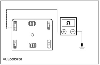
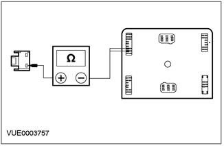
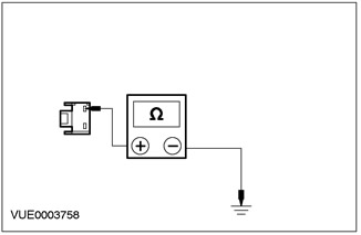
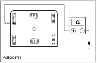
Checking the elements
1. Remove the relay.
2. Connect one end of the auxiliary wire to pin 85 of the relay. Connect the other end of the auxiliary wire to «mass».
3. Connect one end of the second auxiliary wire to pin 86 of the relay.
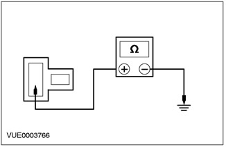
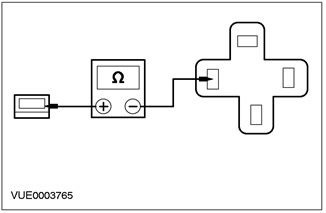
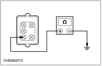
4. Connect one ohmmeter lead to pin 30 of the relay. Connect the second wire to pin 87 of the relay. Measure resistance.
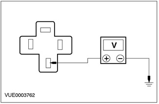
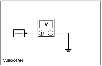
5. Momentarily touch the unconnected end of the auxiliary wire connected to pin 86 to the positive battery terminal. In this case, a distinct click should be heard, and the resistance on the ohmmeter should drop to zero.
6. If a Pinpoint test was performed, return to that Pinpoint test.
Visitor comments