|
STATES |
DETAILS/RESULTS/ACTIONS |
|
A1: CHECK LOW BEAM |
|
|
1 Drive the ON position. |
|
|
2 Turn the light switch to "DOWN LIGHT". |
|
|
3 Check the low beam headlights. |
|
|
• Is the dipped beam on? |
|
|
→ Yes |
|
|
Go to A2 |
|
|
→ No |
|
|
See Section 417-01 for more information. |
|
|
A2: CHECK POWER SUPPLY OF DAYTIME WORK LIGHT RELAY (DRL) |
|
|
1 Enter the OFF position. |
|
|
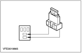
2 Disconnect Daytime running lamp relay (DRL) - C1012. |
|
|
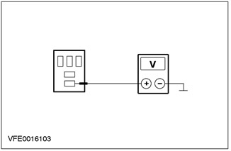
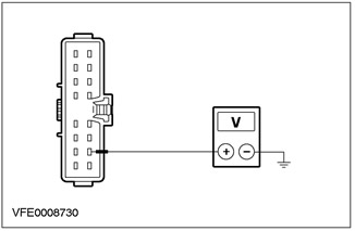
3 Measure the voltage between pin 3 of the C1012 Daytime Work Lamp Relay (DRL), electrical circuit 30-LE7 (red) And "weight". |
|
• Does the battery voltage register? |
|
|
→ Yes |
|
|
Go to A3 |
|
|
→ No |
|
|
REPAIR open circuit between fuse F22 and daytime running lamp relay (DRL), using wiring diagrams. Check if the system is working properly |
|
|
A3: INSPECT DAYTIME WORK LIGHT RELAY CONTROL CIRCUIT (DRL) |
|
|
1 Drive the ON position. |
|

|
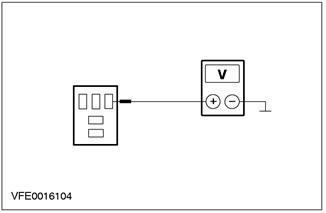
2 Measure the voltage between pin 1 of the C1012 Daytime Work Lamp Relay (DRL) And "weight". |
|
• Does the battery voltage register? |
|
|
→ Yes |
|
|
Go to A4 |
|
|
→ No |
|
|
Go to A6 |
|
|
A4: CHECK CONNECTION WITH "MASS" DAYTIME WORK LIGHT RELAY (DRL) |
|
|
1 Enter the OFF position. |
|
|
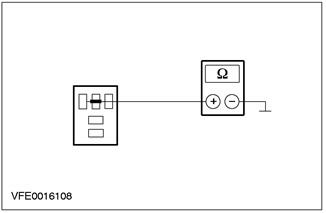
2 Measure the resistance between pin 2 of the C1012 Daytime Work Lamp Relay (DRL) And "weight". |
|
• Is the resistance less than 2 ohms? |
|
|
→ Yes |
|
|
Go to A5 |
|
|
→ No |
|
|
REPAIR open circuit (to her) between daytime working lamp relays (DRL) And "weight" G1 using the wiring diagrams. Check if the system is working properly |
|
|
A5: INSPECT DAYTIME WORK LIGHT RELAY (DRL) |
|

|
1 Connect the jumper wire to connector C1012 of the daytime running lamp relay (DRL), between pin 3, electrical circuit 30-LE7 (red) and pin 5, electric circuit (to her) 15S-LE8 (green/red), 15S-DC19 (green/blue). |
|
2Check the headlights. |
|
|
• Are the daytime running lights on? |
|
|
→ Yes |
|
|
INSTALL a new daytime running lamp relay (DRL). Check if the system is working properly |
|
|
→ No |
|
|
REPAIR open circuit (to her) 15S-LE8 (green/red), between daytime running lamp relay (DRL) and the S120 connection using the wiring diagrams. If necessary, INSTALL a new daytime running lamp resistance. Check if the system is working properly |
|
|
A6: CHECK THE LIGHT SWITCH |
|
|
1 Enter the OFF position. |
|
|
2 Disconnect the Light Switch - C320. |
|
|
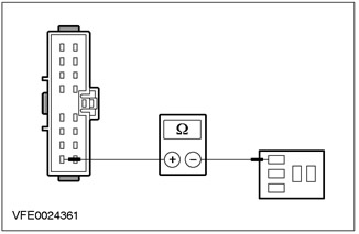
3 Measure the resistance between pin 4 of the C320 light switch, circuit 15S-LE6 (green/yellow), wiring side, and pin 1 C1012 daytime running lamp relay (DRL), electrical circuit 15S-LE6 (green/yellow). |
|
• Is the resistance less than 2 ohms? |
|
|
→ Yes |
|
|
INSPECT the light switch as described in item test: Refer to Section 417-01 for more information. If necessary, INSTALL the new element. Check if the system is working properly |
|
|
→ No |
|
|
REPAIR open circuit (to her) between pin 4 C320 of the light switch and the daytime running lamp relay (DRL), using wiring diagrams. Check if the system is working properly |
|
PINPOINT TEST B: DAYTIME WORK LIGHTS ILLUMINATE WITH IGNITION OFF
|
STATES |
DETAILS/RESULTS/ACTIONS |
|
B1: INSPECT DAYTIME WORK LIGHT RELAY (DRL) |
|
|
1 Enter the OFF position. |
|
|
2 Disconnect Daytime running lamp relay (DRL) - C1012. |
|
|
3Check the headlights. |
|
|
• Are the daytime running lights on? |
|
|
→ Yes |
|
|
Go to B5 |
|
|
→ No |
|
|
Navigate to B2 |
|
|
B2: INSPECT DAYTIME WORK LIGHT RELAY CONTROL CIRCUIT (DRL) |
|

|
1 Measure the voltage between pin 1 of the C1012 Daytime Work Lamp Relay (DRL), electrical circuit 15S-LE6 (green/yellow) And "weight". |
|
• Does the battery voltage register? |
|
|
→ Yes |
|
|
Go to B3 |
|
|
→ No |
|
|
INSTALL a new daytime running lamp relay (DRL). Check if the system is working properly |
|
|
B3: INSPECT DAYTIME WORK LIGHT RELAY CONTROL CIRCUIT (DRL) SHORT TO POWER SUPPLY |
|
|
1 Disconnect the Light Switch - C320. |
|
|
2 Measure the voltage between pin 1 of the C1012 Daytime Work Lamp Relay (DRL), electrical circuit 15S-LE6 (green/yellow) And "weight". |
|
• Does the battery voltage register? |
|
|
→ Yes |
|
|
REPAIR short to circuit power supply (to her), connected to pin 1 C1012 daytime running lamp relay (DRL), using wiring diagrams. Check if the system is working properly |
|
|
→ No |
|
|
Go to B4 |
|
|
B4: CHECK LIGHT SWITCH |
|

|
1 Measure voltage between pin 8 C320 of lighting switch, circuit 15-LE29 (green/black), And "weight". |
|
• Does the battery voltage register? |
|
|
→ Yes |
|
|
REPAIR short to circuit power supply (to her), connected to fuse F61 using the wiring diagrams. Check if the system is working properly |
|
|
→ No |
|
|
INSPECT the light switch as described in item test: Refer to Section 417-01 for more information. If necessary, INSTALL the new element. Check if the system is working properly |
|
|
B5: CHECK THE POWER SUPPLY OF THE DAYTIME WORK LIGHTS FOR A SHORT TO THE POWER SUPPLY |
|
|
1 Disconnect Fuse F19 (BJB). |
|
|
2Check the headlights. |
|
|
• Are the daytime running lights on? |
|
|
→ Yes |
|
|
REPAIR short to circuit power supply (to her) 15S-LE8 (green/red) and 15S-DC19 (green/blue), connected to the daytime working lamp relay (DRL), using wiring diagrams. Check if the system is working properly |
|
|
→ No |
|
|
Go to B6 |
|
|
B6: CHECK POWER SUPPLY TO PARKING LIGHTS (DRL) SHORT TO POWER SUPPLY |
|
|
1 Connect Fuse F19 (BJB). |
|
|
2 Detach Light Switch (C320). |
|
|
3Check the headlights. |
|
|
• Are the daytime running lights on? |
|
|
→ Yes |
|
|
REPAIR short to circuit power supply (to her) 15S-LE29 (green/black), connected to fuse F19 using the wiring diagrams. Check if the system is working properly |
|
|
→ No |
|
|
See Section 417-01 for more information. Clearance and parking lights. |
|
PINPOINT TEST C: PARKING LIGHTS DO NOT WORK WITH DAYTIME WORK LIGHTS ON
|
STATES |
DETAILS/RESULTS/ACTIONS |
|
C1: DETERMINE STATE |
|
|
1 Turn the light switch to "PARKING LIGHTS". |
|
|
2 Check parking lights. |
|
|
• Are the parking lights on? |
|
|
→ Yes |
|
|
Go to C2 |
|
|
→ No |
|
|
See Section 417-01 for more information. |
|
|
C2: CHECK FUSE F19 |
|
|
1 Enter the OFF position. |
|
|
2 CHECK Fuse F19 (BJB). |
|
|
3 CHECK FUSE F19 (10 A) |
|
|
• Is the fuse good? |
|
|
→ Yes |
|
|
Go to C3 |
|
|
→ No |
|
|
Install new fuse F19 (10 A). If the fuse blows again, LOCATE and REPAIR the short circuit using the wiring diagrams. Check if the system is working properly |
|
|
C3: CHECK POWER SUPPLY OF F19 FUSE |
|
|
1 Connect Fuse F19 (BJB). |
|
|
2 Drive the ON position. |
|
|
3 Measure voltage between fuse F19 (BJB) And "weight". |
|
|
• Does the battery voltage register? |
|
|
→ Yes |
|
|
Go to C4 |
|
|
→ No |
|
|
REPAIR open circuit (to her) 15S-DC19 (green/blue) between daytime working lamp relays (DRL) and fuse F19 using the wiring diagrams. Check if the system is working properly |
|
|
C4: CHECK CIRCUIT TO LIGHT SWITCH FOR OPEN |
|
|
1 Enter the OFF position. |
|
|
2 Disconnect the Light Switch - C320. |
|
|
3 Disconnect Daytime running lamp relay (DRL) - C1012. |
|
|
4 Connect the jumper wire to connector C1012 of the daytime working lamp relay (DRL) between pin 3, electrical circuit 30-LE7 (red), and pin 5, electrical circuit (to her) 15S-LE8 (green/red), 15S-DC19 (green/blue). |
|
5 Drive the ON position. |
|
|
6 Measure voltage between pin 15 C320 of light switch, circuit 15S-LE29 (green/black), from the wiring side and "weight". |
|
• Does the battery voltage register? |
|
|
→ Yes |
|
|
TEST the light switch as described in the item checks: Refer to Section 417-01 for more information. If necessary, INSTALL the new element. Check if the system is working properly |
|
|
→ No |
|
|
REPAIR open circuit (to her) 15S-LE29 (green/black) between fuse F19 (BJB) and light switch using the wiring diagrams. Check if the system is working properly |
|
Visitor comments