|
STATES |
DETAILS/RESULTS/ACTIONS |
|
D1: CHECK LOW BEAM |
|
|
1 Drive the ON position. |
|
|
2 Turn on the low beam headlights. |
|
|
3 Check the low beam headlights. |
|
|
• Is the dipped beam on? |
|
|
→ Yes |
|
|
Go to D2 |
|
|
→ No |
|
|
Section 417-01 Headlights, |
|
|
D2: DETERMINING VEHICLE EQUIPMENT |
|
|
1 Determine the equipment of the car. |
|
|
• Does the car have regular headlights? |
|
|
→ Yes |
|
|
Go to D3 |
|
|
→ No |
|
|
Xenon headlights: Go to D9 |
|
|
D3: FUSE CHECK F25 (BJB) |
|
|
1 Enter the OFF position. |
|
|
2CHECK Fuse F25 (BJB). |
|
|
3 Check fuse F25 (20 A) |
|
|
• Is the fuse good? |
|
|
→ Yes |
|
|
Go to D4 |
|
|
→ No |
|
|
INSTALL a new fuse F25 (20 A) and TEST the system. If the fuse blows again, LOCATE and REPAIR the short circuit using the wiring diagrams. CHECK the system is working properly. |
|
|
D4: CHECK THE ELECTRICAL POWER CIRCUIT OF THE F25 FUSE (BJB) |
|
|
1 Connect Fuse F25 (BJB). |
|
|
2 Drive the ON position. |
|
|
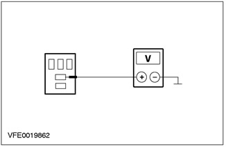
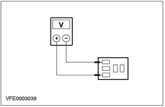
3 Measure voltage between fuse F25 (BJB) and "mass". |
|
|
• Does the battery voltage register? |
|
|
→ Yes |
|
|
Go to D5 |
|
|
→ No |
|
|
REPAIR open circuit 30-DC25 using the wiring diagrams (red), between splice S102 (battery powered) and fuse F25. CHECK the system is working properly. |
|
|
D5: DAYTIME HEADLAMP RELAY POWER SUPPLY CHECK (DRL) |
|
|
1 Enter the OFF position. |
|
|
2 Disconnect the C1012 daytime running lamp relay (DRL). |
|
|
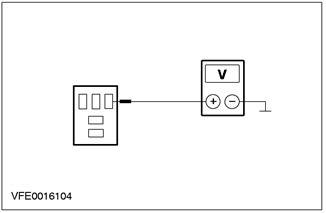
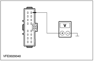
3 Measure the voltage between pin 5 of connector C1012, daytime running lamp relay (DRL), electrical circuit 30-LE8 (red), from the BJB side, and "mass". |
|
• Does the battery voltage register? |
|
|
→ Yes |
|
|
Go to D6 |
|
|
→ No |
|
|
REPAIR open circuit 30-LE8 using the wiring diagrams (red) (DTRL resistor wire) between fuse F25 and the daytime running lamp relay (DRL) CHECK the system is working properly. |
|
|
D6: DAYTIME HEADLAMP RELAY CONTROL ELECTRICAL CIRCUIT CHECK (DRL) |
|
|
1 Drive the ON position. |
|
|
2 Measure the voltage between pin 1 of connector C1012 of the daytime running lamp relay (DRL), electrical circuit 15S-LE6 (yellow-green), from the BJB side, and "mass". |
|
• Does the battery voltage register? |
|
|
→ Yes |
|
|
Go to D7 |
|
|
→ No |
|
|
Go to D8 |
|
|
D7: DAYLIGHT RELAY GROUND ELECTRICAL CHECK (DRL) |
|
|
1 Enter the OFF position. |
|
|
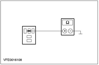
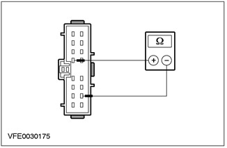
2 Measure the resistance between pin 2 of the C1012 connector of the daytime running lamp relay (DRL), electrical circuit 91-LE6 (black and yellow), from the BJB side, and "mass". |
|
• Is the resistance less than 2 ohms? |
|
|
→ Yes |
|
|
INSTALL a new daytime running lamp relay (DRL). CHECK the system is working properly. |
|
|
→ No |
|
|
REPAIR open circuit 91-LE6 using the wiring diagrams (black and yellow) between the daytime running lamp relay (DRL) and splice S118 (earth point G1). CHECK the system is working properly. |
|
|
D8: LIGHT SWITCH TEST (VEHICLES WITH CONVENTIONAL HEADLIGHTS) |
|
|
1 Enter the OFF position. |
|
|
2 Connect C1012 daytime running lamp relay (DRL). |
|
|
3 Disconnect the C320 light switch. |
|
|
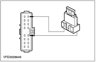
4 Install fusible jumper wire (20 A) into connector C320 of the light switch, between pin 4, circuit 15S-LE14 (red-green), and pin 8, electrical circuit 15-LE29 (black and green), from the side of the electrical wiring. |
|
5 Drive the ON position. |
|
|
6 Check the low beam headlights. |
|
|
• low beam headlights (DRL) burning? |
|
|
→ Yes |
|
|
INSTALL a new light switch. CHECK the system is working properly. |
|
|
→ No |
|
|
LOCATE and REPAIR open circuit 15S-LE14 using the wiring diagrams (A) (red-green) and accordingly 15S-LE6 (A) (yellow-green) between light switch and daytime running lamp relay (DRL). CHECK the system is working properly. |
|
|
D9: LIGHT SWITCH TEST (VEHICLES WITH XENON HEADLIGHTS) |
|
|
1 Enter the OFF position. |
|
|
2 Disconnect the C320 light switch. |
|
|
3 Connect C1012 daytime running lamp relay (DRL). |
|

|
4 Install fusible jumper wire (20 A) into connector C320 of the light switch, between pin 4, circuit 15S-LE14 (red-green) and pin 8, electrical circuit 15-LE29 (black and green), from the side of the electrical wiring. |
|
5 Drive the ON position. |
|
|
6 Check the low beam headlights. |
|
|
• Low beam headlights (DRL) burning? |
|
|
→ Yes |
|
|
INSTALL a new light switch. CHECK the system is working properly. |
|
|
→ No |
|
|
LOCATE and REPAIR open circuit 15S-LE14 using the wiring diagrams (red-green) between the light switch and the DTRL connector of connector C907 and respectively in circuit 15S-LE29B (black and green) between pin 2 and pin 4 of connector C907 (connector DTRL). CHECK the system is working properly. |
|
PINPOINT TEST E: DAYTIME LIGHTS ON WITH IGNITION SWITCH OFF
|
STATES |
DETAILS/RESULTS/ACTIONS |
|
E1: CHECK FAULTY STATUS |
|
|
1 Enter the OFF position. |
|
|
2 Disconnect the C1012 daytime running lamp relay (DRL). |
|
|
3 Check the low beam headlights. |
|
|
• Are the low beam headlights constantly on? |
|
|
→ Yes |
|
|
Section 417-01 Headlights, |
|
|
→ No |
|
|
Go to E2 |
|
|
E2: DAYTIME HEADLAMP RELAY CONTROL ELECTRICAL CIRCUIT TEST (DRL) FOR A SHORT CIRCUIT IN THE ELECTRICAL POWER CIRCUIT |
|
|
1 Measure the voltage at connector C1012 of the daytime running lamp relay (DRL) between pin 1, electrical circuit 15S-LE6 (yellow-green), and pin 2, electrical circuit 91-LE6 (black and yellow), by BJB. |
|
• Does the battery voltage register? |
|
|
→ Yes |
|
|
Go to E3 |
|
|
→ No |
|
|
CHECK the daytime running lamp relay (DRL), acting in accordance with the description given in Ch. "Element Check" attached to the wiring diagrams; INSTALL a new one if necessary. If the relay is OK, Section 417-01, Headlights. |
|
|
E3: DETERMINING THE PRESENCE OF A SHORT CIRCUIT IN THE ELECTRICAL POWER CIRCUIT |
|
|
1 Connect C1012 daytime running lamp relay (DRL). |
|
|
2 Disconnect Fuse F59 (CJB). |
|
|
3 Check the low beam headlights. |
|
|
• Low beam headlights (DRL) constantly on fire? |
|
|
→ Yes |
|
|
Go to E5 |
|
|
→ No |
|
|
Go to E4 |
|
|
E4: IGNITION SWITCH TEST |
|
|
1 Connect Fuse F59 (CJB). |
|
|
2 Disconnect the C456 ignition switch. |
|
|
3 Check the low beam headlights. |
|
|
• Low beam headlights (DRL) constantly on fire? |
|
|
→ Yes |
|
|
Using the wiring diagrams, LOCATE and REPAIR short to power in circuit between ignition switch and fuse F59 (CJB). If necessary, INSTALL a new CJB. CHECK the system is working properly. |
|
|
→ No |
|
|
Install a new ignition switch. CHECK the system is working properly. |
|
|
E5: DETERMINING THE PRESENCE OF A SHORT CIRCUIT IN THE ELECTRICAL POWER CIRCUIT |
|
|
1 Disconnect the C320 light switch. |
|
|
2Check low beam headlights. |
|
|
• Low beam headlights (DRL) constantly on fire? |
|
|
→ Yes |
|
|
Vehicles with conventional headlights: Using the wiring diagrams, LOCATE and REPAIR short to power in circuit 15S-LE6 (A) (yellow-green) and respectively 15S-LE14 (A) (red-green) between the daytime running lamp relay (DRL) and light switch. CHECK the system is working properly. |
|
|
Vehicles with xenon headlights, with DTRL: Go to E7 |
|
|
Vehicles with xenon headlights, without DTRL: Section 417-01, Headlights. |
|
|
→ No |
|
|
Go to E6 |
|
|
E6: CHECK LIGHT SWITCH CIRCUIT FOR SHORT TO POWER CIRCUIT |
|
|
1 Measure the voltage between pin 8 of connector C320, light switch, circuit 15-LE29 (black and green), from the wiring side, and "ground". |
|
• Does the battery voltage register? |
|
|
→ Yes |
|
|
Using the wiring diagrams, LOCATE and REPAIR short to power in the circuit between fuse F59 (CJB) light switch and multifunction switch. If necessary, INSTALL a new CJB.. CHECK the system is working properly. |
|
|
→ No |
|
|
INSTALL a new light switch. CHECK the system is working properly. |
|
|
E7: DETERMINING THE PRESENCE OF A SHORT CIRCUIT TO THE ELECTRICAL POWER CIRCUIT |
|
|
1 Disconnect C907 daytime running lamp connector (DTRL). |
|
|
2Check low beam headlights. |
|
|
• Low beam headlights (DRL) constantly on fire? |
|
|
→ Yes |
|
|
Section 417-01 Headlights, |
|
|
→ No |
|
|
Parking lights do not illuminate: Using the wiring diagrams, LOCATE and REPAIR short to power in circuit 15S-LE14 (red-green) and respectively 15S-LE29 (black and green) between the light switch and connector C907 of the DTRL connector. CHECK the system is working properly. |
|
|
Side Lights Illuminated: Section 417-01, Side Lights, Tail Lights, and Illumination Lamps. |
|
PINPOINT TEST F: SIDE LIGHTS DO NOT WORK WITH DAYLIGHTS ON
|
STATES |
DETAILS/RESULTS/ACTIONS |
|
F1: DEFINING STATE |
|
|
1 Turn on the SIDE LIGHTS. |
|
|
2 Check the parking lights. |
|
|
• Are the marker lights on? |
|
|
→ Yes |
|
|
Go to F2 |
|
|
→ No |
|
|
Section 417-01 Marker Lights, Tail Lights, and License Plate Lamps |
|
|
F2: 15S-LE29 ELECTRICAL CIRCUIT CHECK (BLACK GREEN) LIGHT SWITCH FOR BREAK |
|
|
1 Enter the OFF position. |
|
|
2 Disconnect the C320 light switch. |
|
|
3 Drive the ON position. |
|
|
4 Measure the resistance at light switch connector C320 between pin 15, circuit 15S-LE29 (black and green), and pin 4, electric circuit 15S-LE14 (red-green), from the side of the electrical wiring. |
|
• Is the resistance less than 2 ohms? |
|
|
→ Yes |
|
|
INSTALL a new light switch. CHECK the system is working properly. |
|
|
→ No |
|
|
REPAIR open circuit 15S-LE29 using the wiring diagrams (black and green) and respectively 15S-LE14A (red-green) between connector C906 of the DTRL connector (and respectively C907, with xenon headlights) and light switch. CHECK the system is working properly. |
|
Visitor comments