Contents: Removal ↳ Installation ↳
Special tool
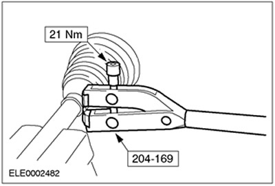
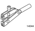 | Device for tightening the clamps of covers 204-169 (14-044) |
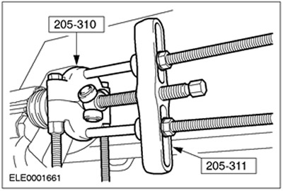
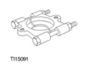 | Bearing/Gear Puller 205-310 (15-091) |
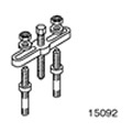 | Bearing/Gear Puller 205-311 (15-092) |
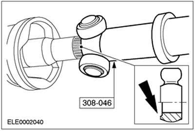
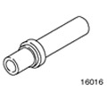 | 308-046 (16-016) 308-046 (16-016) |
General equipment
- Clamp key (Hazet 1847-1)
- Adjustable Locking Ring Pliers
| Name | Specification |
| Internal joint grease | XS4C-M1C230-BA |
Removal
1. Remove the drive axle shaft. For more information, refer to the Left Axle Shaft / Right Axle Shaft chapter in this section.
2.
CAUTION: Use a vise with jaw guards.
NOTE: Clamp the intermediate shaft in a vice.
Clamp the constant velocity joint in a vice and remove the tripod joint housing.
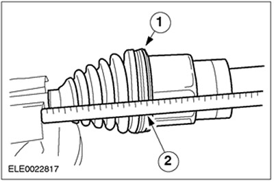
- 1. Cut the cover clips and discard them as no longer needed.
- 2. Pull the cover back.
3. Disconnect the tripod joint.
- Remove the grease.
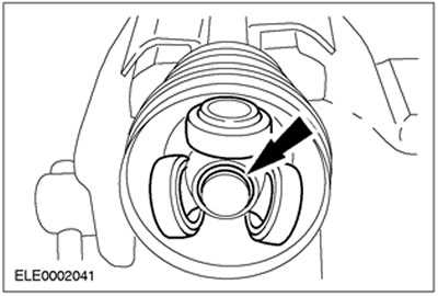
4. Remove the retaining ring.

5. Disconnect the tripod joint using the special tool.
- Remove the cover and discard it as no longer needed.
Installation
1. Install the new cover.
2.
NOTE: Replace the boot clip.
Install the new inner cover clamp using the special tool.
3.
NOTE: Chamfer faces towards the front axle shaft.
Install the tripod joint using the special tool.
- Put the cover on.
- Install the tripod joint into place on the front drive axle shaft.
4.
NOTE: Use a new snap ring.
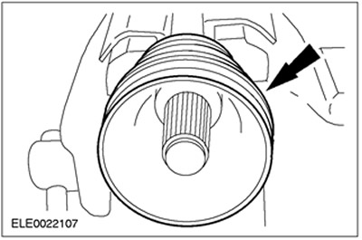
Install the tripod joint spring ring.
5.
CAUTION: Do not pack more than 120 g of grease into the CV joint.
Fill the constant velocity joint with grease.
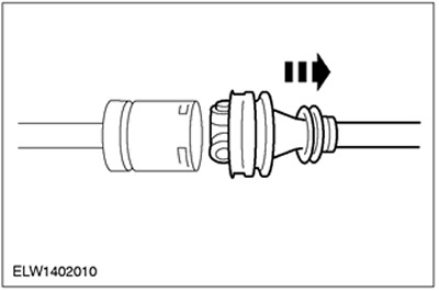
6. Assemble the constant velocity joint.
- 1. Insert a small screwdriver under the edge of the protective cover to release air.
- 2. Slide the constant velocity joint until it stops, then pull it back 20 mm.

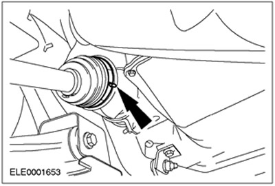
7.
NOTE: Replace the boot clip.
Install the new outer boot clamp using an adjustable wrench.
8. Install the drive axle shaft. For more information, refer to the Left Axle Shaft / Right Axle Shaft chapter in this section.