Disassembly
1. Remove the oil supply and return lines from the hydraulic booster. Plug the ends of the lines with plugs.
2. Disconnect the ball joint ends from the steering rods after loosening the lock nuts.
3. Remove the casing mounting clamps and protective casings from the transmission housing.
4. Move the rack from stop to stop to remove any oil remaining in the hydraulic booster.
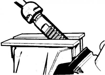
5. Move the rack to the extreme position and clamp the rack (by the teeth) in a vice.
6. Remove the steering rod mounting clamps and disconnect the steering rods from the gear rack.
7. Unscrew the pusher cover bolts, remove the cover, remove the adjusting linings, spring and pusher.
8. Unscrew the lower plug from the steering gear drive pinion housing.
9. Unscrew the steering gear drive pinion lock nut.
10. Mark the position of the drive pinion corresponding to forward movement, as well as the protrusion of the toothed rack on both sides of the housing.
11. Remove the steering gear pinion housing and bearing retaining ring.
12. Remove the steering gear drive pinion from the housing together with the bearing.
13. Rotate the right bearing race until the retaining ring appears on the end of the housing.
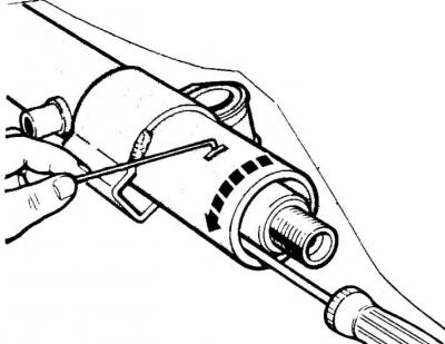
14. Remove the rack retaining ring.
15. Remove the toothed rack, support sleeve, bearing and gasket.
Checking the toothed rack
1. Check the condition of the interacting surfaces:
- sealing ring with steering gear drive shaft;
- teeth of the rack and pinion, as well as the working surface of the pusher;
- teflon seal of the steering gear separator valve.
2. Check and flush hydraulic lines and channels:
- pipelines and a by-pass channel in the rack housing;
- dividing valve.
3. Replace worn or damaged parts and lubricate the edges of the sealing rings with Calipsol grease.
Caution! The Teflon ring of the separating valve nipple should be dipped in boiling water immediately before installation so that it can be positioned correctly.
Caution: The steering gear pinion and the separator valve are supplied in pairs and must be replaced together.
Assembly
1. Install a new drive pinion gasket in the housing, as well as a new ring (using tool 13.010). The cavity of the tool hole should be at the height of the upper plane of the drive pinion housing.
2. Insert the nylon spacer ring and rack seal using a bushing of the appropriate diameter.
3. Lubricate the toothed rack with 40 grams of consistent grease.
4. Install the toothed rack together with the bearing and support sleeve in the housing.
5. Install a new retaining ring through the hole in the housing. Secure its hook to the support sleeve.
6. Install the toothed rack in the middle position and secure it in accordance with the markings made during the process of disassembling the transmission.
7. Secure the bearing and sealing ring longitudinally using a retaining ring.
8. Install the bearing housing filled with solid grease.
9. Screw the lock nut onto the bottom of the steering gear drive pinion.
10. Place the pusher in the rack housing.
11. Place the indicator in the bracket (15.046 and 15.009) on the marking plate. Set the indicator arrow to zero.
12. Mount the indicator on the pusher and its measuring tip on the body. Record the maximum reading (A) of the indicator when moving the toothed rack from one extreme position to the other.
13. The thickness (E) of the adjusting shims to be installed under the tappet cover is equal to the measured value (A) increased by the maximum design clearance (F): E = A F, where F = 0.125 mm.
14. Install the pusher spring, clearance adjusting shims, gasket and screw on the cover.
15. Move the toothed rack to the extreme position and clamp it in a vice.
16. Connect the steering rods to the toothed rack and install new steering rod clamps.
17. Install the rubber protective covers and secure them with new mounting clamps.
18. Connect the ends with ball joints to the steering rods and secure them from unscrewing with lock nuts.
(For details, please visit the website FORDBOOK.RU)