Mark the steering rod so that it can be installed in its original position during assembly. Using special tool 13.009 A, unscrew plug 8 (Fig. 5.7), remove spring 7 and stop 6.
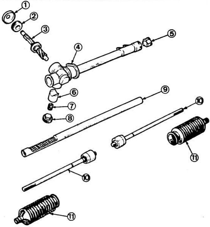 Fig. 5.7. Steering gear parts of cars produced since May 1983.
1 - mudguard ring; 2 - drive gear cover; 3 - drive gear; 4 — steering gear housing; 5 — rack guide bushing; 6 - emphasis; 7 - spring; 8 — stop nut; 9 — rack; 10 — steering rods; 11 - protective covers.
Using the same tool, unscrew the drive pinion mounting nut and remove the gasket. Remove drive pinion 3 with the bearing. Turn the rack and remove it from the crankcase. Remove guide bushing 5 of the rack from the crankcase.