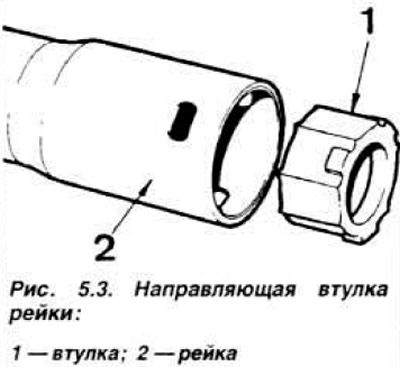
Install, if necessary, a new thrust bushing into the steering gear housing and insert the rack into the housing. Install the bearing and drive pinion into the housing, having first set the pinion to the middle position.
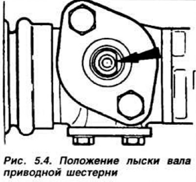
NOTE: After installation, the drive pinion flat should be perpendicular to the rack axis (Fig. 5.4) and facing to the right.
Install the gasket and cover, then the oil seal. Make sure that the cover is located in the center of the drive gear. Apply sealant to the cover mounting bolts and tighten them to a torque of 1.7-2.4 kgf·m. Install the dial indicator on the stop and move its leg to the surface of the crankcase, to which the stop cover is adjacent (Fig. 5.5).
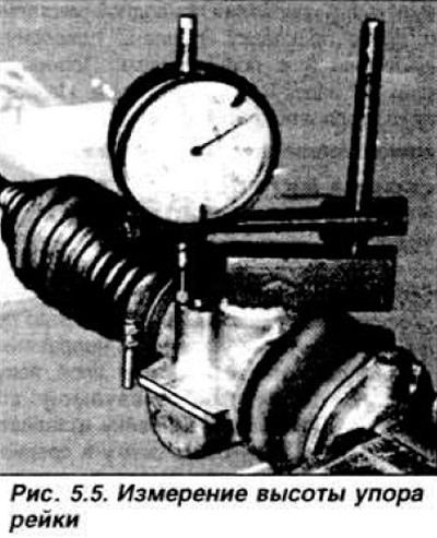
By moving the rack from one extreme position to the other, note the maximum difference in the instrument readings. Select the adjusting washers so that their total thickness is greater than the obtained difference in readings by 0.05-0.125 mm. Example: the difference in measurements is 0.80 mm. The recommended gap is 0.015-0.150 mm. The required thickness of the washers together with the gasket is 0.815-0.950 mm. Install the stop, spring, selected washers, gasket and cover and adjust the gap between the stop and the rack as described in the next paragraph. Install the axial joint bearing pads, steering rods, joint housings and locknuts on the rack. Before installation, lubricate the joints, tie rod bearing pads and axial joint housings. Adjust the tightening of the joints as follows: tighten the locknuts of the joint housings, hook a hook at a distance of 6 mm from the end of the threaded part of the steering rod, fix the other side of it on a spring balance (Fig. 5.6) and measure the force of rotation of the joint from the "straight ahead" position (from the axis of the steering gear housing).
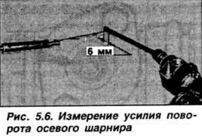
Loosen the lock nut and adjust the position of the hinge body so that the force is equal to 2.3 kgf. Tighten the lock nut. Punch and drill a hole of half the diameter in the hinge body, half in the body of the lock nut with a diameter of 4.0 mm and a depth of no more than 9.5 mm (fig. 5.2). Drill new holes even if the old holes are aligned. Install new pins and punch them around the circumference. Lubricate the mating surface of the protective boot on the steering gear housing and install the boot. Apply 95 cm³ of semi-liquid grease according to Ford SAM-1 C-9106 A specification and move the rack to distribute the grease evenly. Install the second protective boot. Measure the torque of resistance to rotation of the drive pinion as described below.