There are two fuse boxes. The central fuse box is located at the rear of the engine compartment on the driver's side. An additional fuse box is located depending on the year of manufacture of the car or in a separate niche above the glove box (up to 1/92), or in the rear of the engine compartment on the passenger side next to the driver.
Cars up to 1/92
Location of relay and fuse boxes
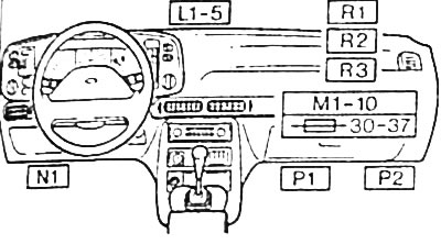
L1 - 5
Modules and relays are located on the holder at the back of the instrument panel in the center of the car.
- L1 - warning light system
- L2 - rear fog lights
- L3 - accelerator time relay (only with automatic transmission)
- L4 - fuel pump (air conditioning system or cooling fan)
- L5 - anti-theft and security system
M1 - 10
The relays are located on the holder at the back of the instrument panel on the passenger side next to the driver.
- M1 - intake air preheating system (carbureted engine) or fuel pump (injection system)
- M2 - self-holding relay or valve injectors (injection system)
- M3 - windshield heating system
- M4 - time relay of the windshield heating system
- M5 - cooling fan
- M6 - pump (anti-lock braking system)
- M7 - anti-lock braking system (main relay)
- M6 - electrical control (ABS module)
- M9 - ride height control system
- M10 - idle control system (air conditioning system)
N1
The module is located on a holder under the instrument panel on the driver's side.
- N1 - incandescent lamp control system or taxi alarm system
R1 - 2
The modules are located under the instrument panel on the passenger side next to the driver.
- P1 - brake and anti-lock system
- P2 - injection fuel pump
R1 - 3
The modules are located on a holder behind the instrument panel on the passenger side next to the driver.
- R1 - automatic system for maintaining a given speed
- R2 - warning signal
- R3 - rear seat maintenance system
S1
The relay is located on the left pillar in the engine compartment.
- S1 - preheating system (diesel engine)
Central fuse box
The position of the relay and fuses is stamped on the back of the fuse box cover.
Location of fuses in the central box
| № | Ampere | Electricity consumer |
| 1 | 20 | High beam headlight left, auxiliary headlight left |
| 2 | 20 | High beam headlight right, auxiliary headlight right |
| 3 | 10 | Dipped beam headlight left |
| 4 | 10 | Dipped beam headlight, right, headlight beam angle adjustment system |
| 5 | 10 | Marker lights, left |
| 6 | 10 | Marker lights, right |
| 7 | 15 | Interior lighting, license plate lights |
| 8 | 15 | Controls: air conditioning systems, heated windshield systems, ride height control systems |
| 9 | 30 | Headlamp cleaning system, tailgate lock |
| 10 | 20 | Central locking system, interior lighting, clock, electric door mirror |
| 11 | 30 | Fuel pump (air conditioning system), taxi alarm system |
| 12 | 10 | Hazard Light System |
| 13 | 30 | Seat heating system, cigarette lighter |
| 14 | 30 | Sound signal |
| 15 | 30 | Wiper motors, windshield washer pumps |
| 16 | 30 | Heated rear window glass and exterior mirrors |
| 17 | 20 | Fog lights |
| 18 | 30 | Heating fan motor |
| 19 | - | absent |
| 20 | 15 | Turn signal lights, reversing lights |
| 21 | 15 | Brake signals |
| 22 | 10 | Electrical circuits and instrumentation on the instrument panel |
| 23 | 30 | Power windows for front doors and sliding roof panel |
| 24 | 30 | Power windows for rear doors and rear seatbacks |
Location of the relay in the central fuse box
| № | Switchable electrical circuit |
| I | Ignition and starter lock on the steering column |
| II | Heated rear window glass and exterior mirrors |
| III | Power windows for front doors and sliding roof panel |
| IV | absent |
| V | Rear wiper |
| VI | Intermittent front wipers |
| VII | Headlight washer system |
| VIII | Interior lighting off delay system |
| IX | Rear door lock switch |
| X | high beam headlights |
| XI | Auxiliary engine running relay |
| XII | Start inhibit switch |
| A | absent |
| IN | absent |
| C | Sound signal |
| D | Rear door lock |
| E | absent |
| F | dipped beam |
| G | Seat heating system |
| H | Fog lights |
Additional fuse box
An additional fuse box is located in a separate niche above the glove box. To replace the fuse, open the glove box and fold down the cover of the holder located above it.
Location of fuses in the additional box
| Color | Ampere | Electricity consumer |
| Black | 20 | Petrol injection pump |
| Pink | 30 | Cooling fan |
| Yellow | 20 | Anti-lock braking system |
| Green | 30 | Anti-lock braking system (pump) |
| Brown | 30 | Windshield heating system (time) |
| Brown | 30 | Windshield heating system |
| Grey | 30 | Electric rear seatbacks |
| Orange | 20 | Ride Height Control System |
| Violet | 15 | Oxygen sensor (car with catalytic converter) |
Cars since 2/92
Location of relay and fuse boxes
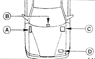
A. Additional relay and fuse box
B. Additional relay under the instrument panel
C. Central fuse and relay box
D. Additional turnip in the engine compartment
Additional fuse box
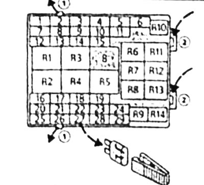
Location of fuses in the central box
| № | Ampere | Electricity consumer |
| 1 | 15 | Fog lights, heated door mirrors |
| 2 | 5 | Parking lights left, license plate lights |
| 3 | 10 | Light switch |
| 4 | 10 | Dipped beam headlight, right, headlight beam angle adjustment system |
| 5 | 10 | Dipped beam headlight left |
| 6 | 30 | Electric seat |
| 7 | 25 | Wiper motors, windshield washer pumps |
| 8 | 5 | Radio |
| 9 | 15 | Sound signal |
| 10 | 15 | High beam headlight left |
| 11 | 15 | High beam headlight, right |
| 12 | 5 | Marker lights, right |
| 13 | 20 | Egnition lock |
| 14 | 15 | Turn signal lights, reversing lights, brake lights |
| 15 | 7.5 | Rear fog lights |
| 16 | 7.5 | Electronics |
| 17 | 7.5 | Electronics |
| 18 | - | absent |
| 19 | 20 | Headlight cleaning system |
| 20 | 20 | Rear window heating system |
| 21 | 10 | Heated exterior mirrors |
| 22 | 20 | Security and anti-theft system, central locking system |
| 23 | 5 | Dashboard lighting |
| 24 | 10 | Interior lighting, radio/audio |
| 25 | 30 | Power windows |
| 26 | 30 | Electric drive of windows of forward doors |
| 27 | 10 | Airbag, ABS |
| 28 | 30 | Electric drive for the sliding roof panel and power windows in the rear doors |
| 29 | 10 | Heating fan motor |
Turnip location in the central fuse box
| № | Switchable electrical circuit |
| R1 | Rear wiper |
| R2 | Intermittent front wipers |
| R3 | dipped beam |
| R4 | Rear window heating system |
| R5 | Interior lighting off delay system |
| R6 | high beam headlights |
| R7 | Absent |
| R8 | Headlight cleaning system |
| R9 | Fog lights |
| R10 | Sound signal |
| R11 | Start inhibit switch (only with automatic transmission) |
| R12 | Rear door lock switch |
| R13 | (Jumper) |
| R14 | absent |
Additional relays
- Diesel engine preheating relay. - in the engine compartment -D-
- Security and anti-theft relay, ABS relay, - in the cabin -B- (up to 8/94)
- Accelerator relay for automatic transmission, -B-
- Power window relay, - in the driver's door
- Intermittent rear wiper relay (TURNIER), turn signal interrupt relay, - near steering column
- Seat heating relay, - in the center console
- Sliding roof panel motor relay, - in the sliding roof panel
- Heating fan motor relay, headlamp cleaning system, cruise control system, air compressor - on the holder behind the glove box
Additional fuse box
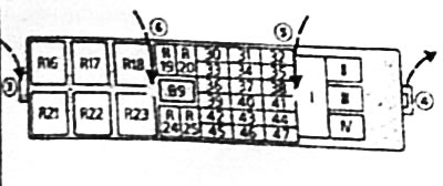
Location of fuses in the additional box
| № | Ampere | Electricity consumer |
| 30 | 20 | Ride Height Control System |
| 31 | 3 | EEC IV ignition module |
| 32 | - | absent |
| 33 | 20 | Power steering, ride height control, heating system, air conditioning system |
| 34 | 15 | Engine run relay |
| 35 | 30 | Cooling fan motor |
| 36 | 10 | Economy battery |
| 37 | 20 | Engine management system |
| 38 | 30 | Windshield heating system (on the right side) |
| 39 | 30 | Cooling fan motor |
| 40 | 25 | Oxygen sensor |
| 41 | 30 | Windshield heating system (From the left side) |
| 42 | 15 | Fuel pump |
| 43 | 20 | Cigarette lighter, seat heating system |
| 44 | 30 | Cooling fan motor 2 |
| 45 | 10 | Hazard Light System |
| 46 | 30 | Anti-lock braking system (module) |
| 47 | 30 | Anti-lock braking system (pump) |
| I | 80 | Power supply circuit of the central fuse box |
| II | 60 | Power supply circuit of the central fuse box |
| III | 60 | Power supply circuit of the central fuse box |
| Iv | 50 | Diesel engine preheating system |
Location of the relay in the additional fuse box
| № | Switchable electrical circuit |
| R16 | Economy battery |
| R17 | Fuel pump |
| R10 | Windshield heating system |
| R19 | Engine operation |
| R2O | Ride Height Control System |
| R21 | Egnition lock |
| R22 | (Jumper) |
| R23 | (Jumper) |
| R24 | Air conditioning system |
| R25 | - |
Visitor comments