Withdrawal
1. Disconnect the negative battery cable (chapter 5 paragraph 1).
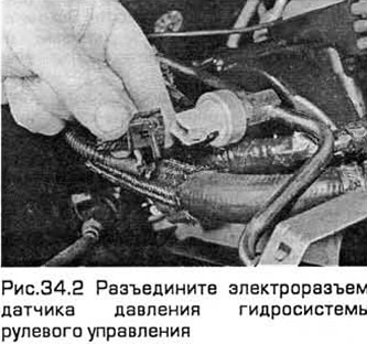
2. Disconnect the power steering pressure sensor connector (see fig.34.2).
Models with 4-cylinder engines
3. Turn out a bolt of fastening of the pipeline to a load-lifting arm of the engine located from its right side.
4. Remove the bolt securing the tubing support to the pump bracket.
5. Place a drip tray under the pump.
6. Release a collar and disconnect a hose of a supply to the liquid pump from an inlet branch pipe. Plug the hose to keep dust and dirt out.
7. Turn away a nut of connection of the pipeline of forcing. The liquid must drain into the container.
8. Apply the parking brake, raise the front of the vehicle and place it on stands. Remove the right front wheel.
9. Turn out bolts and remove the bottom cover of a drive of auxiliary units.
10. Use a wrench to turn the accessory drive belt tensioner clockwise to relieve belt tension. Then remove the belt from the pulleys (see chapter 1).
11. Turn out four bolts and remove the pump from its arms. To access the bolts on the right side of the engine, rotate the pump pulley so that the axes of the pulley holes align with the axes of the bolts.
Models with V-shaped 6-cylinder engines
12. Turn out a bolt of fastening of the pipeline to the right support of the engine.
13. Place a drip tray under the pump.
14. Turn away a nut of connection of the pipeline of forcing located before the right support of the engine. The liquid must drain into the container.
15. Disconnect the drain hose from the fluid pump located behind the engine mount. Plug the hose to keep dust and dirt out.
16. Before removing the engine mount, you need to create a support for it on the right side using a lift. If you use a jack for this, then install it under the pallet, laying a reliable wooden gasket between them.
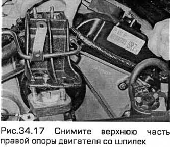
17. Release the high voltage wire retainer. Then, after hanging the engine, gradually loosen the 6 nuts securing the upper part of the right engine mount. Remove the support from the studs (see fig.34.17).
18. Drain the liquid from the cooling system (Chapter 1). Preventing fluid leaks, disconnect the hoses from the reserve tank of this system.
19. On the tank, disconnect the fluid level sensor connector.
20. Turn out bolts and remove a tank.
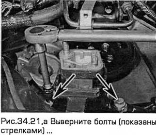
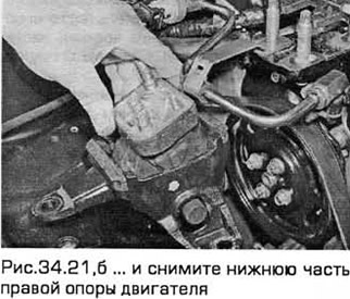
21. Turn out bolts and remove the lower part of the right support of the engine from the inside of a wing (see fig. 34.21, a, b).
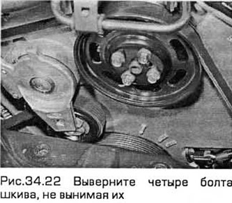
22. While holding the pump pulley with a hex wrench, remove the four pulley bolts without removing them (see fig.34.22).
23. Apply the parking brake and loosen the right wheel nuts. Remove the front wheel.
24. From under the wheel well, remove the screws for the front and rear sections of the accessory drive belt cover.
25. Using a suitable tool, turn the accessory drive belt tensioner clockwise to relieve belt tension. Then remove the belt from the pump pulley.
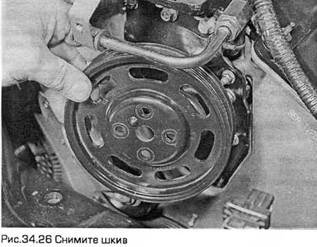
26. Remove the pump pulley bolts and remove the pulley (see fig.34.26).
27. Remove the pump piping bracket bolt and slide the bracket out of the way.
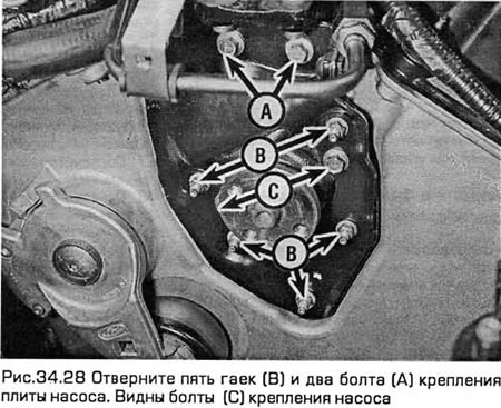
28. Turn off five nuts and two bolts of fastening of a plate of the pump (see fig.34.28).
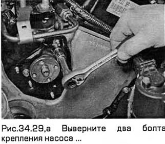
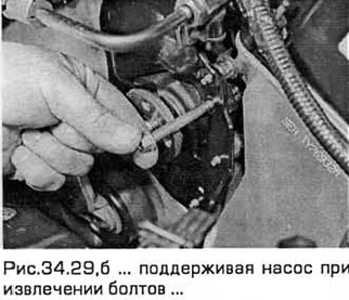
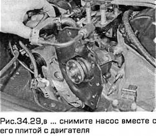
29. Turn out two bolts of fastening of the pump and remove the pump together with its plate from the engine (see fig. 34.29, a-c).
Installation
30. If necessary, the O-ring on the discharge side of the pump can be replaced (the same as stated in paragraph 30).
Models with 4-cylinder engines
31. Install the pump on the bracket and secure it with four bolts, tightening them to the required torque.
32. Put the accessory drive belt on the pulleys. Then turn the belt tensioner clockwise so that the tensioner pulley is in contact with the belt. Release the tensioner to tension the belt.
33. Install the lower belt cover.
34. Install the right front wheel and lower the car to the ground.
35. Connect the pump discharge line and tighten the line nut.
36. Connect the fluid supply hose to the pump with the nozzle and tighten the clamp.
37. Install the pipeline support on the pump bracket and tighten the bolt.
38. Install the pipeline support on the right side of the engine lifting bracket and tighten the bolt.
Models with V-shaped 6-cylinder engines
39. Install the pump with its plate and tighten the bolts and nuts to the required torque.
40. Install the pipeline bracket and tighten the bolt.
41. Install the pump pulley and tighten the bolts to the required torque, holding the pump shaft from turning with a hexagon wrench.
42. Inspect the belt. If necessary, replace it. Slide the accessory drive belt over the pulleys. Then turn the belt tensioner clockwise so. so that the tensioner pulley is in contact with the belt. Release the tensioner to tension the belt.
43. Install the accessory drive belt covers. Install the wheel. Lower the vehicle to the ground and tighten the wheel nuts to the required torque.
44. Install the lower part of the engine mount and tighten the bolts to the required torque (chapter 2A or 2B).
45. Install the reserve tank from the inside of the wing. Repair wiring and hose connections.
46. Install the top of the engine mount onto the studs. Torque tighten 6 nuts (chapter 2A or 2B). Fix the high voltage wire.
47. After installing the engine mounts, remove the lift.
48. Connect the drain hose and the discharge pipeline to the pump, tighten the fitting to the required torque.
49. Install and tighten the pipeline mounting bolt on the motor support.
50. Fill the cooling system (Chapter 1).
All models
51. Connect the negative battery cable.
52. Bleed the hydraulic system (paragraph 33).
Visitor comments