Warning: All models are fitted with an airbag. Follow the precautions in chapter 12.
Withdrawal
1. Disconnect the negative battery cable (chapter 5 paragraph 1).
Warning: As a precaution, pause (at least 15 min) in case of unintentional deployment of the airbag. This is the time needed to dissipate the charge of the capacitor.
2. Turn the steering wheel to the straight ahead position.
Warning: Store the airbag face down in a safe place.
3. Pull out the ignition key. Then turn the steering wheel slightly to lock the steering lock.
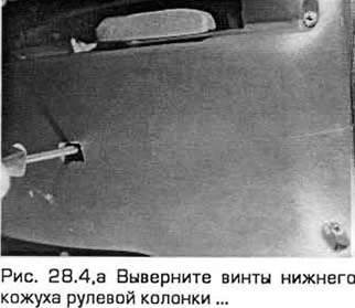
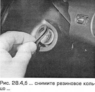
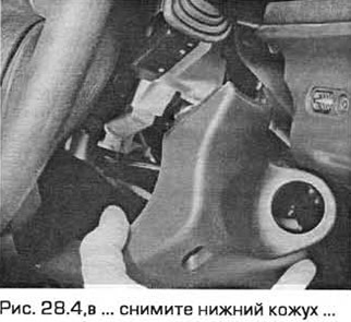
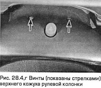
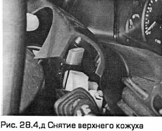
4. Turn out screws and remove the top and lower casings of a steering column. When removing the lower casing, you will need to remove the rubber ring from the ignition / steering lock (see fig. 28.4, a-d).
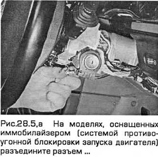
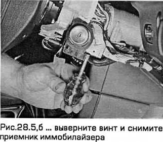
5. On models equipped with an immobilizer (anti-theft engine start blocking system), remove the immobilizer receiver from the ignition switch. To do this, disconnect the connector and remove the screw (see Fig. 28.5, a, b).
6. Remove the lower part of the facing from the front panel on the driver's side (chapter 11).
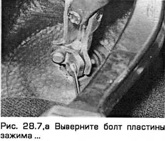
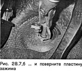
7. Turn out a bolt of a plate of a clip of fastening of a steering shaft to an elastic coupling. Rotate the clamp plate, disengaging the plate and lug of the flexible coupling (see fig. 28.7, a, b).
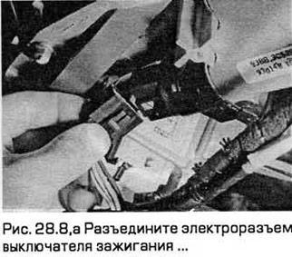
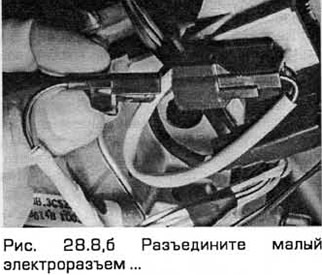
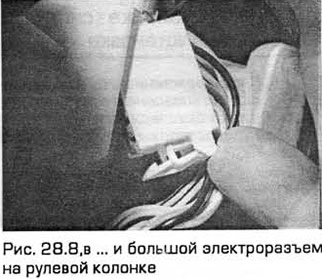
8. Release the wiring on the steering column from the connection and disconnect the electrical connectors (see fig. 28.8, a-c).
9. Turn away a nut and disconnect the lower support of a column.
10. On left-hand drive models, disconnect the airbag connector and release its wiring.
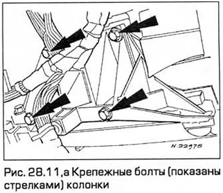
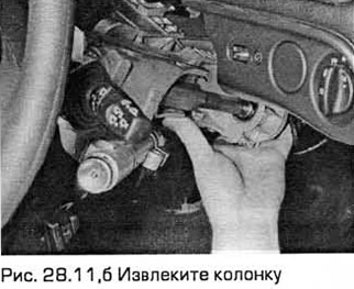
11. Turn out fixing bolts of a column. Then pull the column up to release the locking tab from the groove of the cross member bracket and remove the column from the vehicle (see fig. 28.11, a, b).
Examination
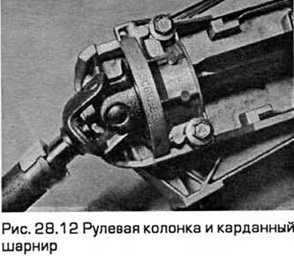
12. After removing the steering column, check the cardan joints for wear, and the upper and lower casings for damage or dents (see fig. 28.12). The column is replaced as a set.
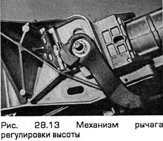
13. Check column height adjustment lever mechanism for wear and damage (see fig. 28.13).
14. With the steering lock open, turn the steering shaft and check the upper and lower bearings for smooth operation. The bearings can be replaced separately if necessary. Disassembling and assembling the column is a fairly simple operation.
Installation
15. Establish a steering column on an arm so that the stopper has entered into a flute.
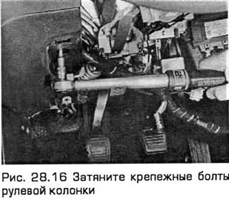
16. Tighten the fixing bolts to the required torque (see fig. 28.16).
17. Install the electrical connectors and secure the wiring with ties.
18. Install the steering shaft on the flexible coupling. Rotate the clamp plate. Then insert the bolt and tighten it to the required torque.
19. Establish the lower part of facing from the driver's side.
20. Establish the top and lower casings of a steering column.
21. Connect the negative battery cable.
Visitor comments