Withdrawal
1. Disconnect the negative battery cable (chapter 5 paragraph 1).
2. Turn out a bolt of a plate of a clip of fastening of a steering shaft to an elastic coupling. Rotate the clamp plate, disengaging the plate and lug of the flexible coupling.
3. Apply the parking brake, raise the front end and place it on stands. Remove both front wheels.
4. On non-automatic transmission models, disconnect the shift linkage and support rods from the transmission (chapter 7A).
5. Remove the exhaust pipe (chapter 4A).
6. Remove the radiator cap located under it and the lockers of both wheel arches. To do this, unscrew the screws and release the clamps.
7. Disconnect the front bumper brackets and move them to the side,
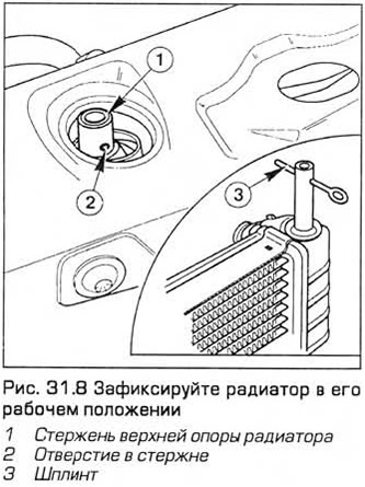
8. Fix the radiator in its working position - insert the cotter pins into the holes of the rods that protrude from the upper radiator supports (see fig. 31.8).
9. Turn out bolts and remove arms of the bottom support of a radiator.
10. Turn out bolts of fastening of the accumulator of an air conditioning system (in the presence of) to the subframe.
11. Working under the vehicle, remove the through bolts from the front and rear engine mounts. On models with automatic transmission, the rear support must be removed.
12. Disconnect the steering hydraulic radiator pipes from the subframe.
13. Remove cotter pins from ball joint nuts on tie rod ends. Then unscrew the nuts. Disconnect the tie rods from the steering knuckles using a ball joint puller. Do not damage the ball joint seals.
14. Working alternately on each side of the vehicle, remove the mounting nuts and remove the anti-roll bar link links from the front suspension struts. Note that on models equipped with ABS, there are ABS sensor wiring brackets under the nuts.
15. Working alternately on each side of the vehicle and taking into account which side the ball joint clamp bolt of the lower front suspension arm is installed, remove this bolt from the steering knuckle. Press the ball joint down and remove it from the steering knuckle. If this is difficult to do, open the joint with a pry bar. Do not damage the ball joint seal.
16. Support the front subframe with two movable (or parallelogram) jacks.
17. Turn out fixing bolts of a subframe. Then lower the subframe just enough to allow access to the steering tubes located on top of it. Note that the front subframe mounting bolts are gold and the rear bolts are silver.
18. Place a container under the steering gear. Then turn away nuts of fastening on the steering mechanism of pipelines of forcing, plum and a radiator. Label the pipelines. Then turn out the bolts of the clamps and disconnect the pipelines so that the liquid flows into the container. Plug the openings in the steering gear and pipes to prevent dust or dirt from getting in.
19. Turn out forward bolts of a subframe and lower it together with the steering mechanism on soil.
20. Where it is necessary to remove a casing of the steering mechanism. Turn out fixing bolts and remove the steering mechanism from a stretcher.
21. With a hex key, unscrew the clamp bolt of the flexible coupling on the input shaft of the steering mechanism and remove the coupling.
22. For instructions on replacing Teflon tracks, see paragraph 30.
Installation
23. Install the flexible coupling on the input shaft of the steering gear. Insert and tighten the clamp bolt with a hex wrench.
24. Install the steering gear on the subframe. Insert the fixing bolts and tighten them to the required torque.
25. Raise the subframe so that the steering pipes can be installed. Tighten nuts and pipe clamps.
26. Raise the subframe so that its mounting holes line up with the bottom holes. At the same time, check that the flexible coupling must sit on the steering gear shaft. A Ford tool is used to align the subframe. After alignment of the subframe, insert and tighten the fixing bolts to the required torque.
27. Install and tighten the front and rear engine mount bolts. On models with automatic transmission, if the rear support is offset from the center of the bracket, loosen the bracket bolts and center the support. Tighten the bracket and support bolts to the specified torque.
28. Working alternately on each side, install the front suspension lower arm ball joint onto the steering knuckle. Insert the clamp bolt with its head facing forward. Install and tighten the nut to the required torque.
29. Working alternately on each side of the vehicle, install the anti-roll bar link and torque-tighten the mounting nuts. On models with ABS, be sure to install the wiring sensor bracket under the nut.
30. Establish spherical hinges of trailers of cross steering drafts on rotary fists. Tighten the nuts to the required torque. The pin holes must line up. If necessary, slightly turn the nut, observing the regulated tightening torque. Insert new cotter pins and straighten them.
31. Insert and tighten the air conditioning accumulator bolts (in the presence of).
32. Establish brackets of the lower support of a radiator and tighten bolts.
33. Pull out the cotter pins that secure the radiator.
34. Install the exhaust pipe (chapter 4A).
35. On non-automatic transmission models, attach the shift linkage and support rods.
36. Install the front wheels and lower the car to the ground.
37. From inside the passenger compartment, attach the steering column clamp plate, then insert the bolt and tighten it to the required torque.
38. Connect the negative battery cable.
39. Bleed the hydraulic steering system (paragraph 33).
40. Check and adjust front wheel alignment as soon as possible (paragraph 36).
Visitor comments