Special tool
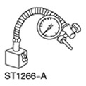 | Stand for dial indicator 100-D002 (D78P-4201-B) |
Examination
1. Loosen wheel nuts.
2. Raise and support the vehicle. See Section 100-02 for more information.
3. Remove the wheel.
4. Remove the brake pads. See Section 206-03 for more information.
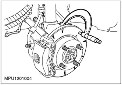
5. To hold the brake disc in place, turn the wheel nuts over and reinstall them.
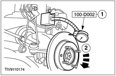
6. Install the dial indicator, mounted on a tripod, on the suspension post.
7.
NOTE: If the runout is not within specification, check the wheel hub end runout.
Using an appropriate dial indicator, measure the runout on the inside and outside of the disc.
- 1. Install the indicator so that it contacts the disc 10 mm from the outer edge.
- 2.Slowly rotate the dial. The total reading of the indicator dial must not exceed the value specified in the specification. For more information, please refer to the chapter Specification available in this section.
8. Check the brake disc thickness difference.
- Using an appropriate micrometer, measure the disc thickness at eight locations 45 degrees apart and 15mm from the outer edge of the brake disc.
- If any of the readings fluctuate by 0.015 mm or more, or the brake disc thickness is less than the prescribed minimum, a new brake disc should be installed.
9. Remove the brake disc. See Section 206-03 for more information.
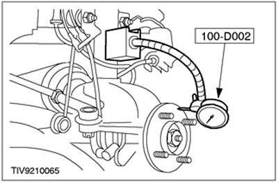
10.
NOTE: Make sure the wheel hub surface is clean and free from rust or foreign material.
Using the special tool, check the end play of the wheel hub.
- Rotate the wheel hub slowly and check for runout. If the runout exceeds the value specified in the specification. Install a new wheel hub and recheck. See Section 204-01 for more information.
11. If the end runout of the hub is within the normal range, install a new brake disc and recheck the runout of the brake disc. See Section 206-03 for more information.
Visitor comments