Withdrawal
Ignition switch and cylinder
1. Disconnect the negative battery cable.
2. Remove the fixing screws (two above and three below) and remove the upper and lower steering column covers.
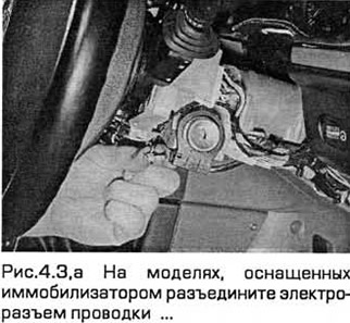
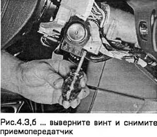
3. On models equipped with an immobilizer, remove the transceiver from the ignition switch by disconnecting the electrical connector and removing the screw (see Fig.4.3, a, b).
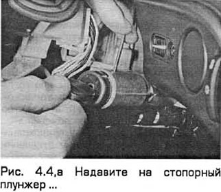
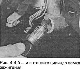
4. Insert the ignition key and turn it to the auxiliary position. Using a small screwdriver or drill through the hole on the side of the lock body, push the locking plunger and pull out the lock cylinder (see fig. 4.4, a, b).
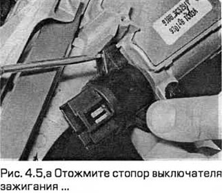
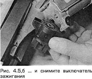
5. The switch can be removed from the steering column. To do this, disconnect the electrical connector, and then press the switch stopper with a screwdriver (see fig. 4.5, a, b).
Windshield wiper multifunction switch
6. Disconnect the negative battery cable.
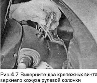
7. Turn out two fixing screws and remove the top casing of a steering column (see fig.4.7).
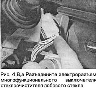
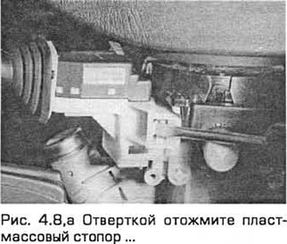
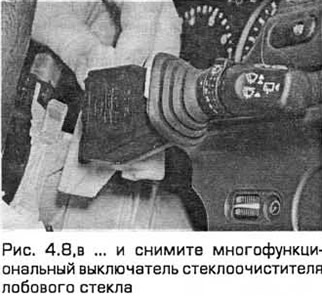
8. Disconnect the electrical connector. Use a screwdriver to press the plastic stopper and pull the switch out of the steering column (see fig. 4.8, a-c).
Switch block for high beam headlights, auxiliary fog lights and rear fog lights
Note: From July 1994 a modified high beam switch is installed. If the modified switch is to be fitted to a vehicle manufactured prior to 1994, an auxiliary wire is required. Please contact your dealer for information.
9. Disconnect the negative battery cable.
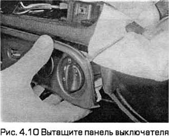
10. Gently pry the switch panel out of the front panel using a screwdriver, placing a rag under it so as not to damage the front panel (see fig. 4.10).
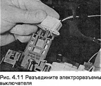
11. Disconnect the electrical connectors and remove the switch panel (see fig. 4.11).
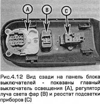
12. Turn out screws and remove the switch from the panel (see fig.4.12).
13. Remove the switch control handle and remove the plug and stopper.
14. Squeeze the plastic tabs and remove the front cover and switch.
Instrument illumination rheostat
15. Disconnect the negative battery cable.
16. Gently pry the switch panel out of the front panel using a screwdriver, placing a rag under it so as not to damage the front panel.
17. Disconnect the electrical connector. Turn out fixing screws and remove a rheostat from the panel.
Headlight Beam Adjuster
18. Disconnect the negative battery cable (chapter 5A).
19. Gently pry the switch panel out of the front panel using a screwdriver, placing a rag under it so as not to damage the front panel.
20. Disconnect the electrical connector on the back of the regulator. Pull the regulator out of the panel.
The switch of the electric drive of the mirror installed on a door
21. Disconnect the negative battery cable.
22. Gently pry the switch panel out of the front panel using a screwdriver, placing a rag under it so as not to damage the front panel.
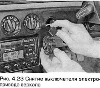
23. Disconnect the electrical connector and remove the switch (see fig.4.23).
Block of switches for direction indicator, dipped beam and flickering signal
24. Disconnect the negative battery cable.
25. Turn out two fixing screws and remove the top casing of a steering column.
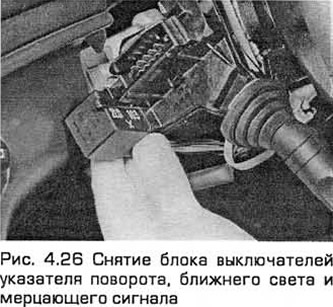
26. Squeeze out the stopper and pull out the switch assembly. Then disconnect the electrical connector (see fig. 4.26).
27. After removing the switches, pull out the turn signal relay (if required).
Horn switch (steering wheel with airbag)
28. Remove the airbag from the steering wheel (paragraph 28).
29. On models with constant speed control, remove the switch components (paragraph 21).
30. Disconnect the electrical connector, then remove the two screws (in the presence of) and remove the switch.
Horn switch (steering wheel without airbag)
31. Disconnect the negative battery cable.
32. Carefully pull out an overlay from an average part of a steering wheel which contains the switch of a sound signal.
33. Disconnect the wiring and pull out the switch.
Radio remote control switch
34. Disconnect the negative battery cable.
35. Turn out two fixing screws and remove the top casing of a steering column.
36. Squeeze out the stopper and pull out the switch assembly. Then disconnect the electrical connector.
Cruise control switch
37. See paragraph 21.
Power window switch (single)
38. Disconnect the negative battery cable.
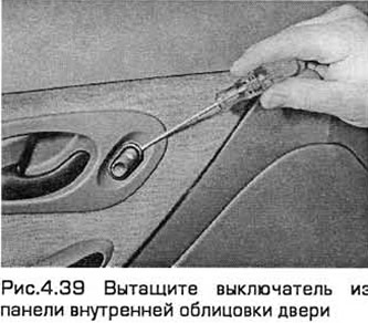
39. Gently pull the switch out of the inner door trim panel, using a rag to avoid damaging the trim (see fig.4.39).
40. Disconnect the electrical connector and remove the switch (see fig.4.40).
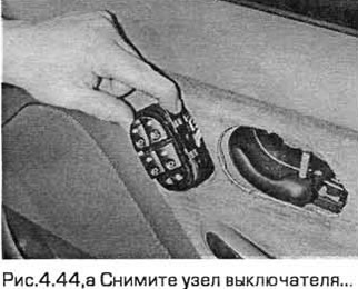
Power window switch (combined) and insulator
41. Disconnect the negative battery cable.
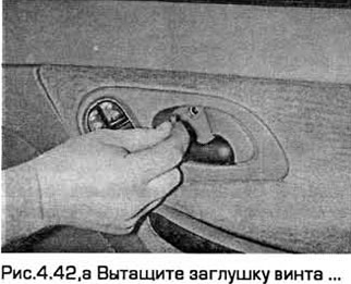
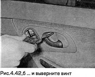
42. Pull out the screw cap located in the opening under the inner door handle. Remove the screw (see Fig. 4.42, a, b).
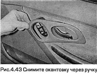
43. While holding the inside door handle in the open position, remove the bezel through the handle (see fig.4.43).
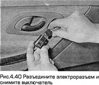
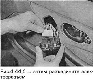
44. Depress the stopper and remove the switch assembly. Then disconnect the electrical connector (see Fig. 4.44, a, b).
Sunroof switch
45. Disconnect the negative battery cable.
46. Gently pull the switch out of the interior door trim panel, using a rag to avoid damaging the trim.
47. Disconnect the electrical connector and remove the switch.
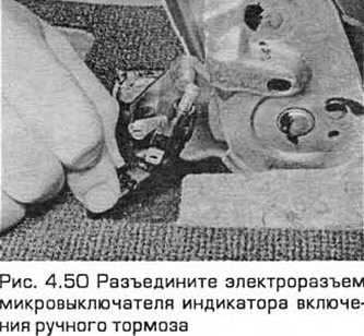
Handbrake indicator microswitch
48. Disconnect the negative battery cable.
49. Remove the central console (chapter 11).
50. Disconnect the electrical connector. Then remove the screw and remove the switch from the handbrake lever support bracket (see fig. 4.50).
Mode switch "economical/sporty" (models with automatic transmission)
51. Disconnect the negative battery cable.
52. Set neutral. Then pull out the selector position indicator panel by placing a rag under the tool so as not to damage the lining of adjacent components.
53. Squeeze the switch out of the panel and disconnect the electrical connector.
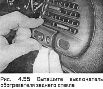
Windshield Defroster Switch and Rear Defroster Switch - Pre-1996 Models
54. Disconnect the negative battery cable.
55. Gently pull the switch out of the interior door trim panel, using a rag to avoid damaging the trim (see fig. 4.55).
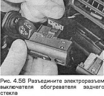
56. Disconnect the electrical connector and remove the switch (see fig. 4.56).
Heated windshield switch and rear window defroster switch - 1997 model year
57. Disconnect the negative battery cable.
58. Carefully pry the main light switch panel out of the front panel with a screwdriver, placing a rag under it so as not to damage the front panel. If needed for access, disconnect the wiring connectors on the switches from the rear.
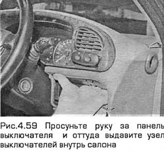
59. Put your hand behind the switch panel and from there squeeze the switch assembly into the passenger compartment, but not vice versa, so as not to damage the switches (see fig.4.59).
60. Disconnect the electrical connectors and remove the switch assembly (see fig. 4.60).

Power seat height adjustment switch (single)
61. Disconnect the negative battery cable.
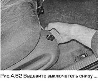
62. Press the switch from below (see fig.4.62).
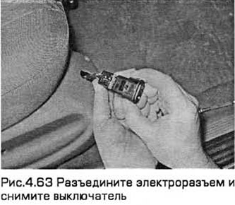
63. Disconnect the electrical connector and remove the switch (see fig.4.63).
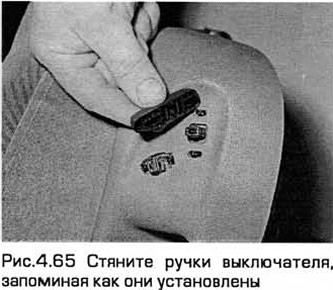
Power seat adjustment switch (two-section)
64. Remove the seat (chapter 11).
65. Pull off the switch handles, remembering how they are installed (see fig.4.65).
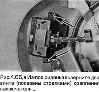
66. From under the seat, unscrew the two screws securing the switch and remove the switch (see fig. 4.66, a, b).
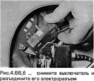
67. Locate the switch electrical connector by tracing the wiring from it to the electrical connector. Disconnect the electrical connector.
Seat heating switch - pre-1996 models
68. See paragraphs 45-47.
Seat heating switch - models since 1997
69. Disconnect the negative battery cable.
70. Pull out the audio block (paragraph 23).
71. Put your hand through the opening of the audio unit and squeeze the switch from there into the passenger compartment.
72. Disconnect the electrical connector and remove the switch.
Traction Control Switch - Pre-1996 Models
73. See paragraphs 45-47.
Traction Control Switch - Models since 1997
74. Disconnect the negative battery cable.
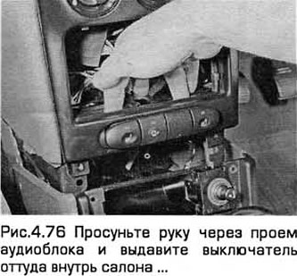
75. Pull out the audio block (paragraph 23).
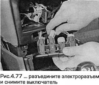
76. Put your hand through the opening of the audio unit and squeeze the switch from there into the cabin (see fig.4.76).
77. Disconnect the electrical connector and remove the switch (see fig.4.77).
Adaptive Suspension Mode Switch
78. See paragraphs 45-47.
Open door alarm microswitch
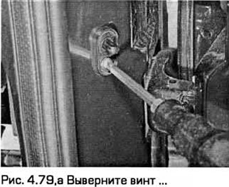
79. Open the door. Then remove the screw and carefully pull the switch out of the rack (see fig. 4.79, a, b).
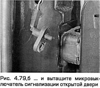
80. Disconnect the wire and tie it up so it doesn't fall into the rack.
Trunk light switch
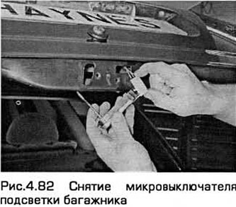
81. To access the switch, it is almost always necessary to remove the lock components (see relevant paragraph chapter 11).
82. Unfasten the switch from the lock, disconnect the connector and remove it from the lock (see fig.4.82).
Fuel cut switch
83 See chapter 4A.
Installation
84. Installation - in the reverse order of removal.
Visitor comments