Note: Before disconnecting or replacing fuses or relays, turn off the ignition and disconnect the corresponding electrical circuit. If you need to remove a fuse or relay, disconnect the negative battery cable. Reconnect the battery according to the instructions chapters 5.
1. Fuses are designed to break a circuit at a certain current value with a circuit to protect components and wiring that could be damaged if the rated current is exceeded. Exceeding the rated current usually occurs due to a circuit fault, which is often caused by a short circuit (see paragraph 2). The main fuse box, which also contains some relays, is mounted below the dashboard on the front passenger side (see Fig. 3.1).
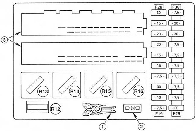 Fig. 3.1. Layout of main fuse box components.
1. Fuse/Relay Extractor Clamp
2. Diode
3. Electrical connectors
2. The central timer module is mounted on the bottom of the main fuse box. This module contains the timing circuits for the rear window defogger, interior lamps, and windshield wiper switch. This module sounds a warning buzzer/chime when you leave the vehicle without turning off the lamps, or when the vehicle is parked with an automatic transmission and the transmission selector is not in the "P" position.
3. The additional fuse box is located in the engine compartment at the front left. To access it, you need to unfasten and remove the cover. The additional fuse box also contains some relays (see Fig. 3.3). Each circuit can be identified by the numbers printed on the main fuse box cover and the additional fuse box cover (on its inside). For a list of circuits protected by fuses, see Technical requirements. There is a plastic clip attached to the main fuse box and to the inside of the sub box cover. This should be used to remove the fuses and relays.
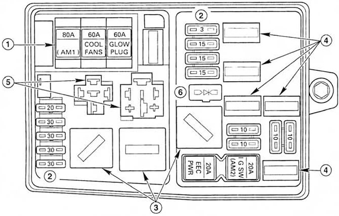 Fig. 3.3. Location of components of the additional fuse box.
1. Fuses 1...3
2. Fuses 4...8, 11...14
3. Relays R2, R5, R6
4. Relay R7...R11
5. Relay sockets R1 and R4
6. Diode
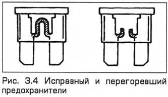
4. To remove the fuse, pull it out of the holder using the plastic clip. Pull the fuse out of the clip by pulling it sideways. If the fuse is blown, you will see that the wire inside it is broken (see Fig. 3.4).
5. Always replace the fuse with a new one of the same rating. Never install a fuse with a higher rating or replace it with wire or foil to prevent damage and fire. The fuse rating is stamped on its head. If the fuse blows again after replacement, be sure to find out the reason for this before installing a new one.
6. Spare fuses of different ratings are located in the cover of the auxiliary box. Please note that if you will not be using the car for a long time, fuse 34 in the main box should be removed to prevent the battery from being discharged when auxiliary electrical components are turned on.
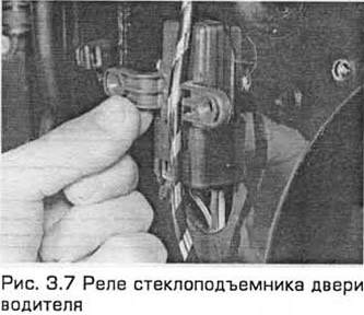
7. Relays are electrically controlled switches installed in specific circuits. To remove a relay, pull it out of its socket. Each relay in the fuse box has a plastic rod on the top surface, which you need to pull the relay out with a plastic clamp. For a list of relays and their functions, see. Technical requirements (see Fig. 3.7).
8. If the component in the circuit in which the relay is installed is faulty due to the relay (as you assume), then listen to the relay while the circuit is running. When the relay is triggered when power is supplied, a click is heard. If the relay is triggered, then the fault is caused by the components or wiring of the system. If the relay does not receive power (no click is heard), then the relay is not supplied with control voltage or the relay itself is faulty. When troubleshooting, pay attention to the contacts of the relay socket. You can check the relay by installing a working relay in its place. In this case, be careful, some relays are similar in appearance, but are designed to perform different functions.
9. The central timer module is installed at the bottom of the main fuse box. This module has a self-diagnosis function. Note that the diagnosis will not be performed if the rear window defroster is faulty.
10. To turn on the system, press the rear window defroster button with the ignition on. Then release the button. Turn on the light switch, the washer pump switch and all the switches located on the doors one by one and make sure that the buzzer confirms the correctness of the input signals.
11. After this, set the windshield wiper lever to the position corresponding to the intermittent operation mode. Monitor the output signals by turning on the same switches.
12. The self-diagnosis function is disabled when the ignition is turned off and is enabled again when it is turned on.