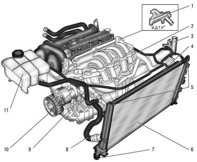
Pic. 5.21. Engine cooling system: 1 - radiator outlet hose; 2 – a liquid hose of a broad tank; 3 - thermostat; 4 - water pump; 5 - expansion tank; 6 - outlet pipe of the water jacket; 7 - inlet hose of the radiator; 8 - shut-off valve; 9 - electric fan; 10 - steam hose of the expansion tank; 11 - radiator
The engine cooling system is liquid, closed type, with forced circulation of liquid. The device of the cooling system is shown in fig. 5.21. The system consists of a cooling jacket, a radiator 11 with an electric fan 9, an expansion tank 5, a water pump 4, a thermostat 3, a water jacket outlet pipe 6, a shut-off valve 8 and hoses.
The circulation of liquid in the system is created by a water pump 4. From the pump, the liquid is supplied to the engine cooling jacket, washes the cylinders of the combustion chamber and then enters the thermostat 3. Depending on the position of the thermostat valve, the liquid either enters the water pump (at low temperature), or into the radiator 11 (at high temperature).
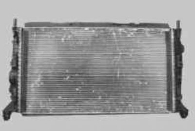
Radiator 11 with horizontal liquid flow, with a tubular-ribbon aluminum core and plastic tanks. There is a drain plug at the bottom of the left radiator tank. In the tanks there are inlet and outlet pipes of hoses to the water jacket of the engine, a pipe of the steam hose 10 connecting the radiator with the expansion tank.
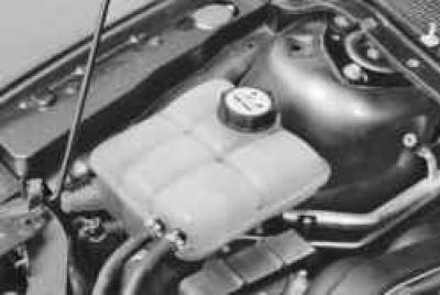
Expansion tank 5 serves to compensate for the changing volume of the coolant depending on its temperature. It is made of translucent plastic. In the plastic stopper of the tank, which closes its neck, inlet and outlet valves are installed.
NOTE: The serviceability of the expansion tank plug valves is very important for the normal operation of the cooling system. However, if problems arise (e.g. boiling coolant) motorists pay attention only to the operation of the thermostat and forget to check the valves. Leakage of the exhaust valve leads to a decrease in the boiling point of the coolant, and its jamming in the closed state leads to an emergency increase in pressure in the system, which can cause damage to the radiator and hoses.
Water pump 4 centrifugal type provides forced circulation of liquid in the cooling system. It is located on the front surface of the cylinder block and is driven by a V-ribbed belt, common with the generator and power steering pump, from the crankshaft pulley. The pump has sealed bearings that do not require relubrication. The pump cannot be repaired, therefore, in case of failure (fluid leakage or bearing damage) it is replaced as an assembly.
Thermostat 3, which is a solenoid valve, maintains the normal operating temperature of the coolant and shortens the engine warm-up time. The thermostat is controlled by the electronic unit of the engine management system, which receives information from the coolant temperature sensor installed on the outlet pipe 6 of the water jacket. The thermostat is installed in a housing fixed to the cylinder head. At a coolant temperature of up to 60°C, the thermostat is completely closed and the liquid circulates through a small circuit, bypassing the radiator, which accelerates the engine warm-up. At a temperature of about 80°C, the thermostat begins to open, and at 98°C it opens completely, providing fluid circulation through the radiator.
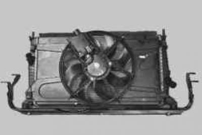
electric fan 9 cooling systems (with plastic eight-bladed impeller) serves for additional airflow of the radiator, turns on and off at the signal of the electronic engine control unit. Moreover, depending on the intensity of the thermal regime and the algorithm of the air conditioner, the electric fan can rotate at low and high speeds. Changing the fan speed mode is provided by the engine control unit by connecting additional resistance. The electric fan assembly with the casing is fixed to the radiator of the cooling system.
Outlet pipe 6 of the water jacket serves to distribute coolant flows depending on the operating modes of the cooling system. A coolant temperature sensor is screwed into the body of the pipe, according to which the electronic unit of the engine control system controls the thermal regime of the engine.
Stop valve 8 is designed to stop the removal of coolant to the expansion tank when starting a cold engine. A closed shut-off valve reduces coolant circulation in a cold engine system, saving fuel when the engine warms up and reduces warm-up time. At a coolant temperature of 80°C, the shut-off valve opens fully and coolant begins to circulate through the expansion tank.
The radiator for the interior heater is also included in the cooling system with hoses.
The system is filled with liquid (antifreeze), that does not freeze at ambient temperatures down to -40°C. Type of coolant filled in the cooling system - Motorcraft Super Plus 4 (Green colour) or Motorcraft Super Plus 2000 (orange color).
WARNING: Motorcraft Super Plus 4 is a non-silicate organic acid based fluid (OAT), and should not be mixed with other types of coolant.
Motorcraft Super Plus 2000 is based on monoethylene glycol, like most modern coolants.
NOTE: The procedure for replacing the coolant is described in Sec. 4 «Maintenance» (cm. «Coolant replacement»).
WARNING: It is not recommended to fill the cooling system with water, as antifreeze contains anti-corrosion, anti-foam and anti-scale additives.
WARNING: Coolant is toxic! Avoid inhalation of vapors and contact with skin.
WARNING: Repair leaks in the cooling system in a timely manner to avoid the ingress of coolant vapors into the vehicle interior during its operation. Your health is more valuable than a new cooling system pipe or a tube of sealant!
The electronic engine control unit contains a program to protect the engine from overheating. At the very beginning of overheating, according to information from the coolant temperature sensor, the engine control unit sends a command to move the arrow of the coolant temperature gauge to the red zone.
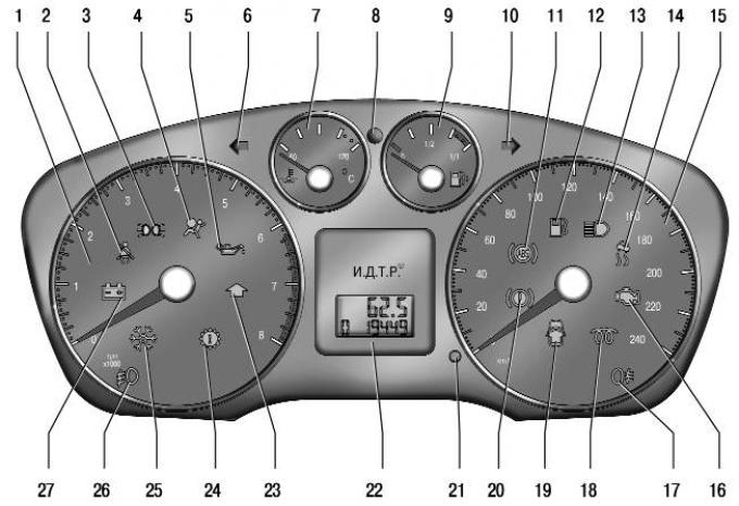
Pic. 1.8. instrument cluster
If the driver does not stop the engine and its temperature continues to rise, the engine control unit turns on the control lamp 16 (see fig. 1.8), this indicates to the driver that the engine is approaching a critical limit and should be stopped.
If the driver ignores the readings of the coolant temperature gauge and the lamp on, the electronic engine control unit cuts off the fuel supply to two engine cylinders and limits the crankshaft speed to 3000 rpm-1. At the same time, signal lamp 24 lights up (see fig. 1.8) engine malfunction, which indicates the possibility of significant engine damage and a sharp increase in exhaust toxicity. In this mode, air is sucked into the deactivated cylinders, which reduces the temperature of the engine. Moreover, the disconnected cylinders alternate with each other for more uniform cooling.
NOTE: If the engine has gone into 2-cylinder mode only, it can only be returned to 4-cylinder mode by turning the ignition off and on again.
If the engine temperature continues to rise even after all the measures taken, the control unit switches off the engine. If at this time the throttle pedal is moved by pressing the foot to a large angle (For example, the driver is overtaking), the engine will stop only 10 seconds after the pedal is released.
Visitor comments