NOTE: It is more convenient to perform the work on a lift. It can also be performed on a vehicle supported by supports.
NOTE: The replacement of the tip is shown using the left steering rod as an example; replace the right tip in the same way.
NOTE: The left end has right-hand threads and the right end has left-hand threads.
1. Raise and support the front of the vehicle on the side of the hub cap being replaced. Remove the wheel.
WARNING: Apply the parking brake and place wheel chocks under the rear wheels.

TIP: If fasteners are very dirty, clean them with a wire brush and treat them with a penetrating lubricant such as WD-40.
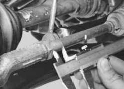
2. Measure and remember the length of the free part of the steering rod thread so that during assembly, if possible, the wheel alignment angle is not disturbed.
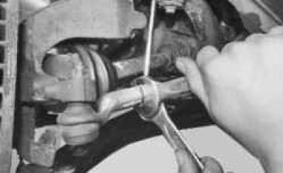
3. Loosen the tie rod end lock nut.
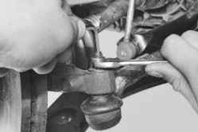
4. Loosen the nut securing the ball joint to the steering knuckle arm, holding the joint from turning.
NOTE: The outer tie rod end ball joint nuts are self-locking. Replace with new nuts each time they are removed.
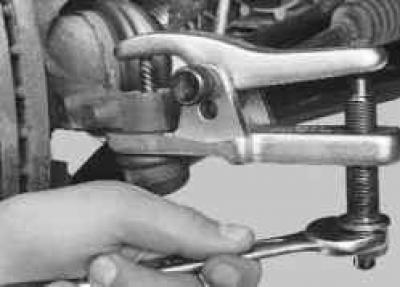
5. Install the ball joint puller…
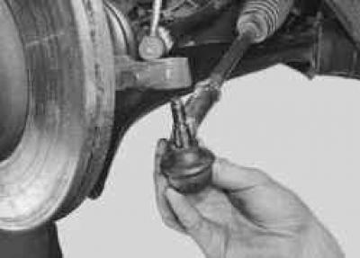
6. …and press the pin out of the pivot arm boss.
USEFUL TIP: If you don't have a puller, you can knock out the ball joint pin by hitting the end of the pivot arm boss with a hammer, striking along the axis of the arm.
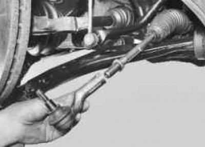
7. Unscrew the tip from the steering rod, counting the number of turns so that when installing a new tip, the wheel alignment does not change as much as possible.
8. Install the new tip in the reverse order of removal, screwing it onto the steering rod by the number of turns that was counted during removal, and tighten the lock nut to the torque specified in Appendix 1.
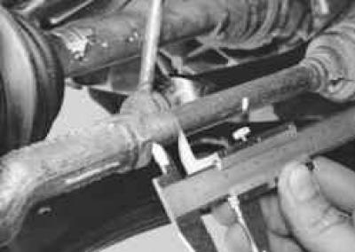
9. Re-measure the length of the free thread of the steering rod. This length should correspond to the value measured in step 2. If this is not the case, loosen the lock nut and either screw on or unscrew the tip, depending on whether the length of the free thread has increased or decreased. Tighten the lock nut and repeat the check.
10. Check and, if necessary, adjust the wheel alignment angles at a service station.
(The text of the article was copied from the website: FORDBOOK.RU)