Contents: Removal ↳ Installation ↳
General equipment:
- Electric drill
- Drill 5 mm
- Cutter for 29mm hole
- Cutter for 35mm hole
- Cutter for 70mm hole
Removal
All cars
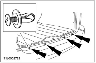
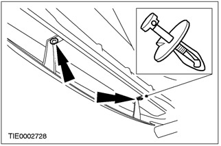
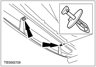
1. Remove the upper push pin retainers.

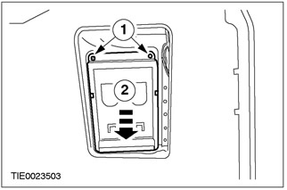
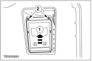
2. Remove the cargo area side trim panel inserts on both sides.
- 1. Remove the screws.
- 2. Move the side trim panel insert down.
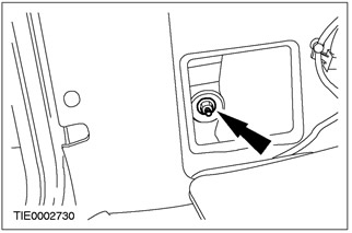
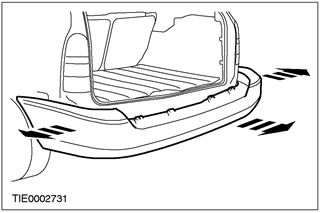
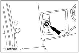
3. Remove the side bumper mounting nuts on both sides.
4. Raise and support the vehicle. Refer to Section 100-02 for additional information.
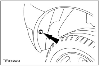
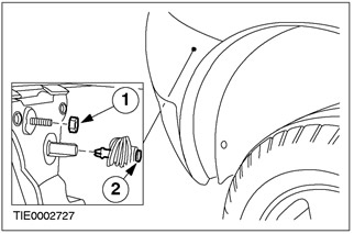
5. Disconnect the bumper from the fender splash guards on both sides.
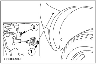
6. Separate the bumper from the fenders on both sides.
- 1. Remove the nut.
- 2. Remove the clamp.
7. Remove the lower push pin retainers.
8. Lower the vehicle.
9.
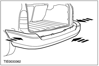
CAUTION: The ends of the bumper must be pulled away from the fenders to avoid damage to the paintwork.
Disconnect the bumper. Disconnect the clamps.

Vehicles with parking assistance system manufactured up to 10.2001.
10.
NOTE: With the help of another technician, support the bumper.
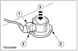
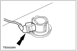
Remove the parking assistance sensors.
- 1. Disconnect the plug connector.
- 2. Press the locking elements.
- 3. Push the sensor through the bumper.
Vehicles with parking assistance system manufactured from 10.2001 onwards.
11.
NOTE: With the help of another technician, support the bumper.
NOTE: If not installing new sensor covers or housings, remove them from the bumper.
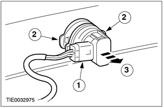
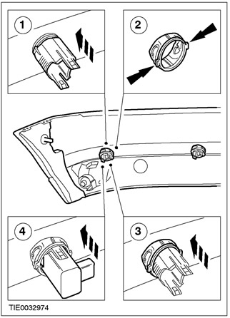
Remove the parking assistance sensors.
- 1. Disconnect the plug connector.
- 2. Press the locking elements.
- 3. Remove the sensor.
Cars with parking assistance system
12.
NOTE: With the help of another technician, support the bumper.
NOTE: Bumper shown removed for clarity.
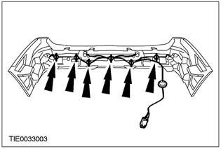
Disconnect the parking assist sensor wiring harness from the bumper filler.
13.
NOTE: Bumper shown removed for clarity.
Remove the bumper filler.

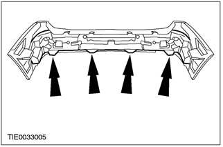
All cars
14. Remove the bumper.
Installation
Cars with parking assistance system
1. Install the bumper filler.

2. Install the bumper.

Vehicles with parking assistance system manufactured up to 10.2001.
3.
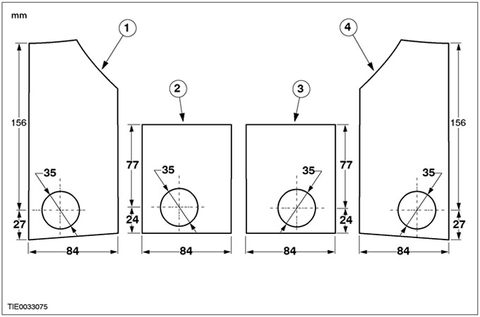
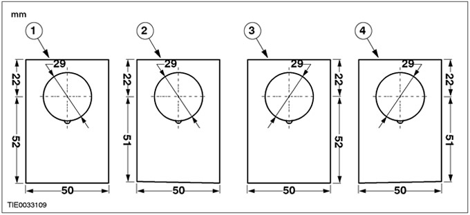
NOTE: Use templates supplied with the manufacturers instructions.
NOTE: Templates are shown for reference.
Cut out the templates for the parking assistance sensor locations.
- 1. Left outer template.
- 2. Left inner template.
- 3. Right inner template.
- 4. Right outer template.
4.
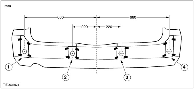
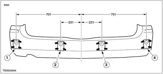
NOTE: Bumper shown removed for clarity.
NOTE: Mark the position of the top and bottom edges of the templates.
NOTE: Positional tolerance ±5mm.
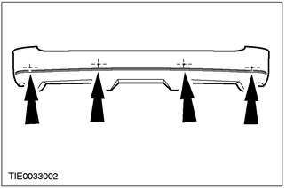
Using suitable tape, attach the parking assist sensor location templates to the bumper as shown in the figure.
- 1. Left outer template.
- 2. Left inner template.
- 3. Right inner template.
- 4. Right outer template.
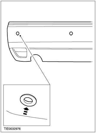
5. Using a suitable punch and hammer, mark the location of the holes for installing the parking aid sensors.
6.
NOTE: Bumper shown removed for clarity.
Using a suitable electric drill and a 35mm hole saw, cut through the bumper (+2mm, -0.0mm).
- 1. Left outer opening.
- 2. Left inner hole.
- 3. Right inner hole.
- 4. Right outer opening.
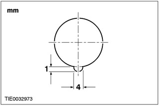
7. Using a suitable round file, make grooves in the bumper to accommodate the parking aid sensor covers as shown in the illustration (+0.5 mm, -0.0 mm).

8.
CAUTION: The ends of the bumper must be pulled away from the fenders to avoid damage to the paintwork.
Remove the bumper. Disconnect the clamps.
9. Remove the bumper filler.

10.
NOTE: With the help of another technician, secure the bumper filler using suitable wood blocks as support.
NOTE: Use the holes made when cutting the holes for installing the parking assist sensors as guides.
Using a suitable electric drill and a 70mm hole saw, cut through the bumper filler.
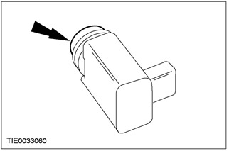
11. Install the parking assistance sensor rings.
12. Install the parking assistance system sensors.
- 1. Install the sensor.
- 2. Press the locking elements.
- 3. Install the clamp.
Vehicles with parking assistance system manufactured from 10.2001 onwards.
13.
NOTE: Use templates supplied with the manufacturers instructions.
NOTE: Templates are shown for reference.
Cut out the templates for the parking assistance sensor locations.
- 1. Left outer opening.
- 2. Left inner hole.
- 3. Right inner hole.
- 4. Right outer opening.
14.
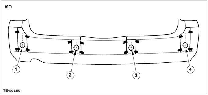
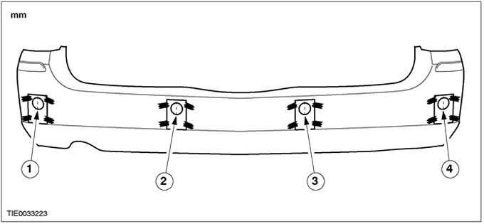
NOTE: Bumper shown removed for clarity.
NOTE: Mark the position of the bottom edges of the templates.
NOTE: Positional tolerance ±5mm.
Using suitable tape, attach the parking assist sensor location templates to the bumper as shown in the figure.
- 1. Left outer opening.
- 2. Left inner hole.
- 3. Right inner hole.
- 4. Right outer opening.
15.
NOTE: Bumper shown removed for clarity.
Using a suitable electric drill and a 29mm hole saw, cut out the bumper.
- 1. Left outer opening.
- 2. Left inner hole.
- 3. Right inner hole.
- 4. Right outer opening.
16. Using a suitable round file, make grooves in the bumper to accommodate the parking aid sensor covers as shown in the illustration (+0.5 mm, -0.0 mm).
17.
CAUTION: The ends of the bumper must be pulled away from the fenders to avoid damage to the paintwork.
Remove the bumper. Disconnect the clamps.

18. Remove the bumper filler.

19.
NOTE: With the help of another technician, secure the bumper filler using suitable wood blocks as support.
NOTE: Use the holes made when cutting the holes for installing the parking assist sensors as guides.
Using a suitable electric drill and a 70mm hole saw, cut through the bumper filler.

20. Install the parking assistance sensor rings.
21.
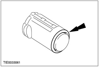
NOTE: Note the difference between the inner and outer parking assist sensor covers.
NOTE: Make sure the parking assist sensor covers are flush with the bumper.
Install the parking assist sensor covers.
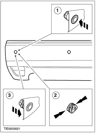
22. Install the parking assistance system sensors.
- 1. Install the housing.
- 2. Press the locking elements.
- 3. Install the clamp.
- 4. Install the sensor.
Cars with parking assistance system
23. Install the bumper filler.
24.
NOTE: With the help of another technician, support the bumper.
NOTE: Bumper shown removed for clarity.
Connect the parking assist sensor wiring harness to the bumper filler.

25.
NOTE: With the help of another technician, support the bumper.
Connect the parking assistance sensor plugs.
All cars
26. Install the bumper.
27. Raise and support the vehicle. Refer to Section 100-02 for additional information.
28. Install the lower push pin retainers.
29. Attach the bumper to the fenders on both sides.
- 1. Install the clamp.
- 2. Install the nut.
30. Attach the bumper to the fender splash guards on both sides.

31. Install the bumper side mounting nuts on both sides.
32. Install the cargo area side trim panel inserts on both sides.
- 1. Move the side trim panel insert upward.
- 2. Install the screws.
33. Install the upper push pin retainers