Contents: Removal the windshield wiper motor ↳ Installing the windshield wiper motor ↳ Removal and installation the… ↳
Windscreen wiper
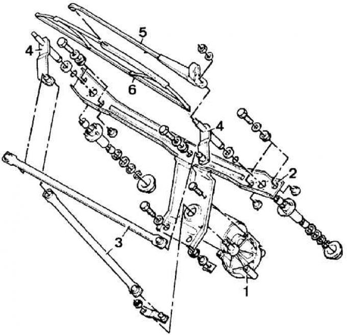
1 – engine, 2 – holder, 3 – rods, 4 – wiper arm axles, 5 – wiper arm, 6 – brush
Removal the windshield wiper motor
1. Turn on the windshield wiper and when the crank fastening nut appears on the engine shaft, turn off the ignition or remove the ground wire from the battery terminal.
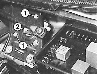
2. Unscrew the crank mounting nut (2) on the engine shaft and remove it. Unscrew the three bolts (1) securing the windshield wiper motor to the bracket.
3. Remove the wiper motor and disconnect the electrical wire connector.
Installing the windshield wiper motor
1. Connect the electrical wire connector to the wiper motor.
2. Insert the wiper motor and tighten the bolts securing the wiper motor to the bracket.
3. Install the crank of the lever mechanism on the engine axle and check whether the crank protrusion fits into the recess of the engine axle.
4. Tighten the nut securing the crank to the engine axle.
5. Connect the ground wire to the battery (if removed) or turn on the ignition and check the correct operation of the windshield wiper.
Removal and installation the windshield wiper linkage
1. Disconnect the ground wire from the battery
2. Tilt the plastic protective cap of the windshield wiper arm upward, unscrew the fastening nut, remove the washer and the windshield wiper arm together with the brush (see fig. Windshield wiper).
3. Repeat the described steps for the second wiper arm.
4. Raise the hood, disconnect the fluid supply lines to the windshield washer nozzles and unscrew one bolt at both ends of the air supply grille into the body.
5. Close the hood and unscrew the eight bolts after removing the plastic covers.
6. Remove the air supply grille inside the body.
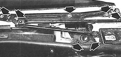
7. Unscrew the seven bolts securing the windshield wiper linkage holder (the arrows show the position of the seven bolts).
8. Remove the holder together with the wiper motor and lever mechanism.
9. Disconnect the electrical wires from the engine.
Attention! The mechanism rods are connected to its cranks by means of nylon ball pins. The pins should be carefully removed using a lever and inserted after coating with graphite grease.
10. To install the lever mechanism, perform the steps in reverse order to the removal process.