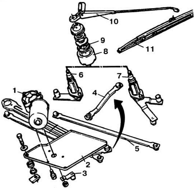
 Fig. 7.72. Windscreen wiper parts.
1 — gear motor; 2 — gear motor mounting plate; 3 — drive lever; 4 and 5 - intermediate levers; 6 and 7 — lever axes; 8 and 9 - elastic hinge of the axle; 10 - leash; 11 - brush.
The brushes move in parallel. The cleaner has three operating modes; low and high speed continuous mode and intermittent movement of brushes The intermittent mode relay is installed in the mounting block. The windshield wiper connection diagram is shown in Fig. 7.73.
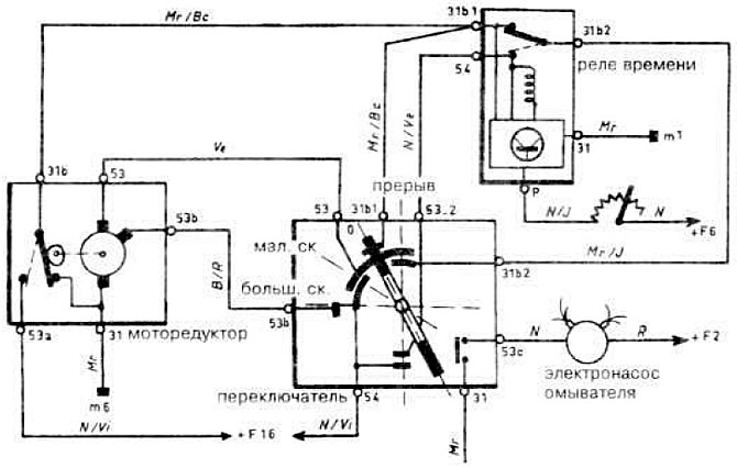 Fig. 7.73. Windshield wiper and washer circuit diagram.
The windshield wiper is controlled by the large right steering column switch; moving up to the first fixed position - low speed operation; by moving the switch up to the second fixed position - operation at high speed, by moving the switch down - operation in intermittent mode. By pressing the button at the end of the switch, the windshield washer electric pump is turned on.