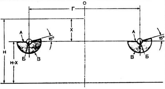
 Fig. 7.70. Headlight adjustment diagram.
A - upper boundary of the light spot; B - center of the light spot (low beam); B - lower boundary of the light spot; H — height of headlights from ground level; G - distance between headlight centers 1004 mm; O - the axle of the car; X=110 mm for "XR3", 130 mm for the rest.
The car must be fully equipped and filled with gas. The tire pressure must be normal. Place the car 10 m from the wall opposite the intersection of the horizontal and vertical lines. Press the suspension to relieve tension in its nodes. Apply a mark in the center of the windshield and rear window. Place the shield on the line formed by the two marks. The horizontal line must be located at a height of H-X, where X=130 mm for all models except the XR3, and 110 mm for the XR3 model.
Open the engine hood and turn on the low beam. Close the left headlight and use the adjusting screws (Fig. 7.71) to adjust the light beam of the right headlight horizontally so that the intersection point of the horizontal and inclined lines "B" is on the vertical line of the marking.
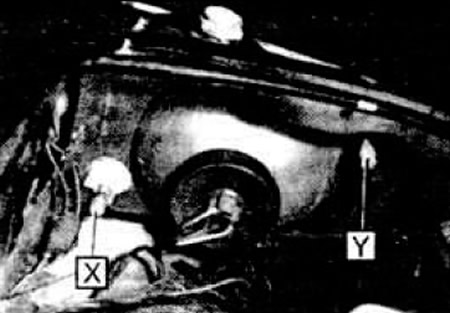 Fig. 7.71. Headlight unit adjustment screws.
1 - screw for adjusting the light beam in the vertical direction; 2 — screw for adjusting the light beam in the horizontal direction.
Adjust the light beam vertically so that line "A" aligns with the intermittent line on the shield. Close the right headlight and adjust the light beam of the left headlight.
The original can be found on this resource: fordbook.ru