Features of the device
The control devices are combined into a cluster of devices, the connections of which are made by means of a printed circuit on a flexible board. On cars of the basic configuration, a cluster of devices is installed, including control lamps of the parking brake, direction indicators, high beam, emergency oil pressure and battery charge, and devices: a speedometer on the left and a fuel level indicator and a coolant temperature indicator on the right. On cars of the GL and XR3 configuration, the arrangement of devices is almost the same, except that a tachometer is installed on the right side of the cluster, and the fuel level and coolant temperature indicators are located in the center of the cluster. The speedometer also has daily and total mileage counters.
The high beam, emergency oil pressure, charging and parking brake and brake fluid level warning lights are located in the center at the top of the cluster. In addition, the cluster has a number of warning lights switched on by a special electronic unit: brake lining wear, windshield washer fluid level (lights up when 1/4 remains), oil level, coolant level and 7 liters of fuel remaining. Some cars were equipped with an economizer with yellow warning lights for increased fuel consumption and red for high fuel consumption. In case of economical fuel consumption, these warning lights do not light. Each of these warning lights is switched on by a vacuum sensor.
Control unit for signal lamps
The VDO control unit is located under the instrument panel and can be accessed through the loudspeaker jack. The unit switches on signal lamps, receiving information from the oil level sensors, washer fluid level, coolant level, fuel level and brake lining wear (Fig. 7.83).
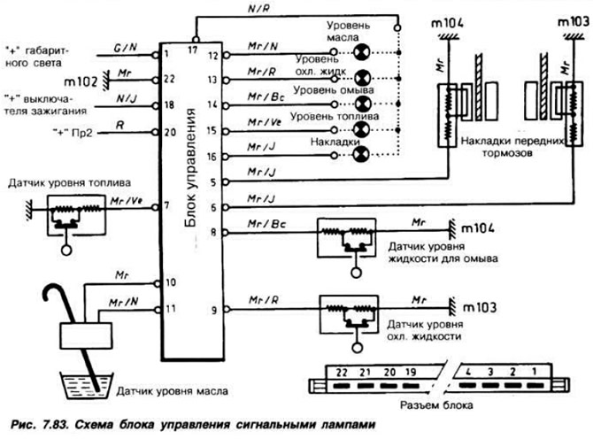
When the ignition is turned on, the lamps glow continuously for 5 seconds if the circuits are in good condition; in the event of a break or short circuit in the circuit, the lamp flashes for 40 seconds and goes out. If the sensor is triggered, the corresponding signal lamp glows continuously until the fault is eliminated. It is clear from the diagram that the operating principle of the sensors is based on measuring resistance, which makes it possible to monitor the integrity of the sensor circuits.
The principle of operation of the oil level sensor is based on measuring the resistance of the sensor thread, through which a current of 0.20 A passes. The resistance of the thread is measured every 1.5 seconds. The obtained result is compared with the previous one. If the sensor thread is cooled by oil, the resistance remains unchanged. If the thread is not immersed in oil, it heats up, its resistance changes. The signal lamp lights up. The resistance of the sensor thread is 7.5-8.5 Ohm. The washer fluid level and coolant level sensors have a float. The conductor of the lining wear sensor is pressed into the lining and rubs when it wears out, causing the signal lamp to light up. The washer fluid level, coolant level and fuel level sensors continue measuring for another eight seconds in case of a decrease in the level in order to avoid false alarms when the car is rocking.
The resistance value of the level and wear sensors is 170-190 Ohm at a normal level and 1350-1450 Ohm in case of a malfunction. Sensor response values:
- fuel level sensor - not less than 7l;
- oil level sensor - 3 mm below the "Min" mark on the dipstick;
- washer fluid level sensor - 1/4 level;
- coolant level sensor - "Min" mark on the expansion tank body;
- brake pad wear sensor - with a pad thickness of 2 mm.
Due to fluctuations in supply voltage, normal operation may be disrupted. To avoid this, it is recommended to connect a 2200-2500 μF capacitor with two insulated poles in parallel with the power supply of the signal lamp control unit, i.e. between terminal 18 (black and yellow wire) and terminal 22 (brown wire).
Removing and installing the instrument cluster
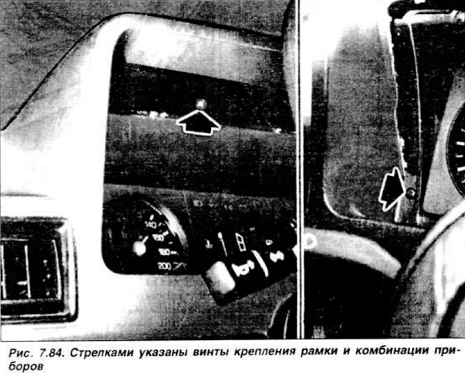
Disconnect the wires from the battery. Loosen the screws securing the instrument cluster frame (Fig. 7.84) and pull it towards you, release the two clamps and separate it from the instrument cluster.
Loosen the two instrument cluster mounting screws. Remove the lower front panel trim, release and remove the speedometer drive flexible shaft. Carefully remove the instrument cluster, moving it forward and to the side to provide access to the connectors. Disconnect the connectors and remove the instrument cluster. Before installing the instrument cluster, connect the connectors, install it in place and secure with two screws. Install and secure the frame. Connect the flexible shaft to the speedometer and install the lower front panel trim. Connect the battery and check the operation of the instruments.