|
STATES |
DETAILS/RESULTS/ACTIONS |
|
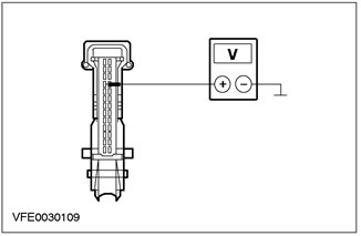
G1: F60 FUSE CHECK |
|
|
1 Enter the OFF position. |
|
|
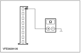
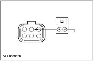
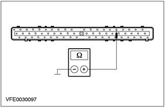
2 CHECK F60 fuse (CJB). |
|
|
• Is the fuse good? |
|
|
→ Yes |
|
|
Go to G2 |
|
|
→ No |
|
|
Install new fuse F60 (7.5 A). If the fuse blows again, LOCATE and REPAIR the short circuit using the wiring diagrams. CHECK the system is working properly. |
|
|
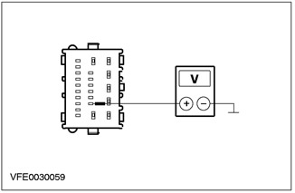
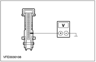
G2: VOLTAGE CHECK ON FUSE AREA F60 |
|
|
1 Connect Fuse F60 (CJB). |
|
|
2 Drive the ON position. |
|
|
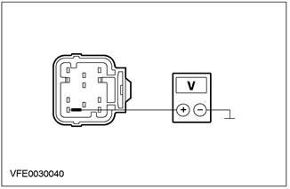
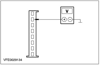
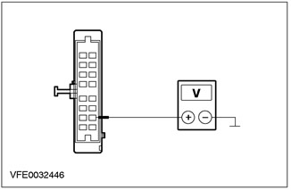
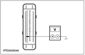
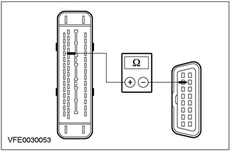
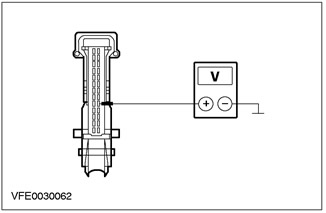
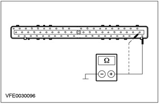
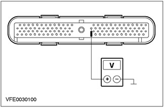
3 Measure voltage between fuse F60 (7.5 A) and "mass". |
|
|
• Does the battery voltage register? |
|
|
→ Yes |
|
|
Go to G3 |
|
|
→ No |
|
|
Using the wiring diagrams, RESTORE power to fuse F60. If necessary, INSTALL a new CJB. CHECK the system is working properly. |
|
|
G3: SYSTEM CHECK USING WDS. |
|
|
1 Enter the OFF position. |
|
|
2 Connect the diagnostic tool. |
|
|
3 Check the system using WDS. |
|
|
• Are any DTCs logged? (DTC). |
|
|
→ Yes |
|
|
Take appropriate action on DTCs as directed by WDS. CLEAR fault memory and CHECK system for correct operation. |
|
|
→ No |
|
|
Go to G4 |
|
|
G4: VOLTAGE CHECK IN AIR BAG MODULE |
|
|
WARNING: To minimize the possibility of premature deployment of airbags, wait at least one minute after disconnecting the harness before disconnecting any connectors from the secondary restraint system (ov) battery mass (ov). Failure to follow this instruction may result in injury. |
|
|
WARNING: To minimize the possibility of premature deployment of the airbag, do not use radio key code savers when operating the secondary restraint system. Failure to follow this instruction may result in injury. |
|
|
1 Enter the OFF position. |
|
|
2 Disconnect the battery ground wire. |
|
|
3 Disconnect the C424 air bag module. |
|
|
4 Connect the battery ground wire. |
|
|
5 Drive the ON position. |
|
|
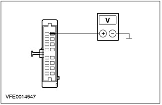
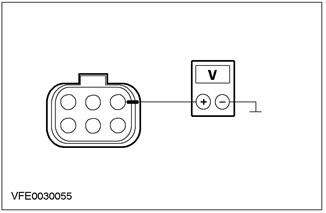
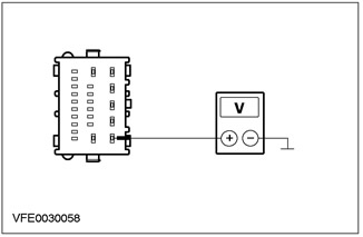
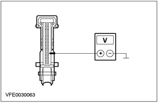
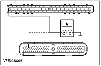
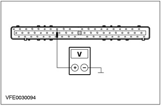
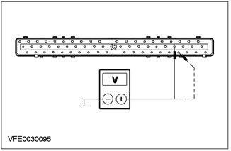
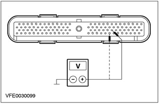
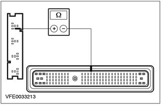
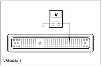
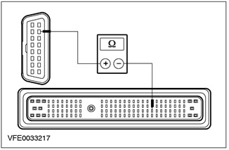
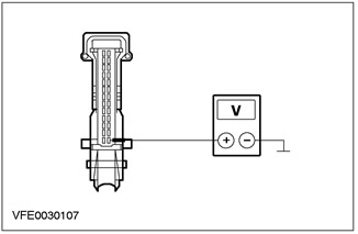
6 Measure the voltage between pin 8 of connector C424 of the airbag module, circuit 15-JA10 (green-orange), from the wiring side, and "ground". |
|
• Does the battery voltage register? |
|
|
→ Yes |
|
|
Go to G5 |
|
|
→ No |
|
|
LOCATE and REPAIR open circuit 15-JA10 (green-orange) between fuse F60 and the airbag module using the wiring diagrams. If necessary, INSTALL a new CJB. CHECK the system is working properly. |
|
|
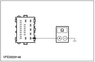
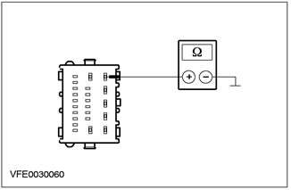
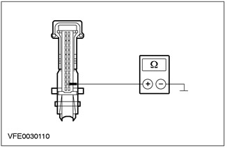
G5: AIR BAG MODULE GROUND CHECK |
|
|
1 Enter the OFF position. |
|
|
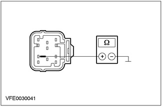
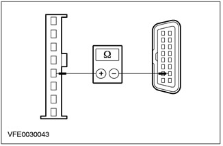
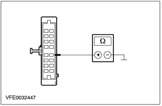
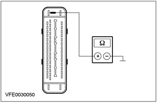
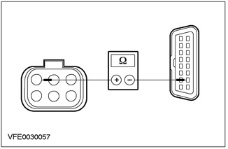
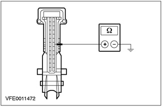
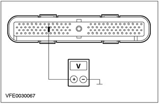
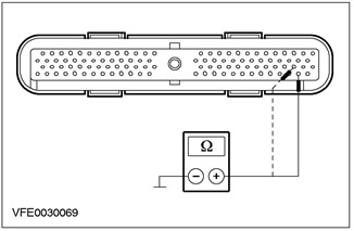
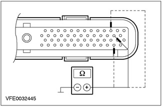
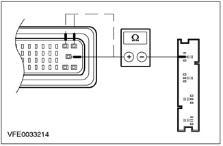
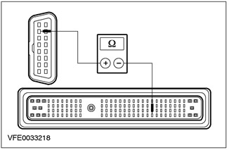
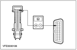
2 Measure the resistance between pin 9 of connector C424 of the airbag module, circuit 91-JA10 (black and red), from the wiring side, and "ground". |
|
• Is the resistance less than 2 ohms? |
|
|
→ Yes |
|
|
Go to G6 |
|
|
→ No |
|
|
LOCATE and REPAIR open circuit 91-JA10 (black and red) between the airbag module and earth point G41 using the wiring diagrams. CHECK the system is working properly. |
|
|
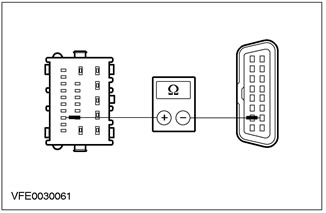
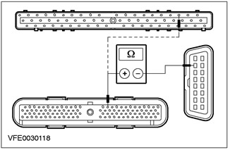
G6: CHECK THE ELECTRICAL CIRCUIT BETWEEN THE AIR BAG MODULE AND THE COMMUNICATION PLUG (DLC) FOR A BREAK |
|
|
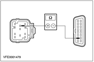
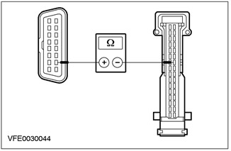
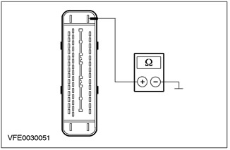
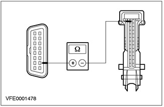
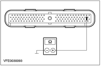
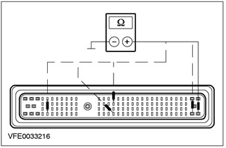
1 Measure the resistance between pin 7 of connector C424 of the airbag module, circuit 8-EE7 (white-red), on the wiring side, and pin 7 of the C200 DLC plug connector, electrical circuit 8-EE10 (white and black). |
|
• Is the resistance less than 2 ohms? |
|
|
→ Yes |
|
|
CHECK the airbag module, INSTALL a new one if necessary. CHECK the system is working properly. |
|
|
→ No |
|
|
LOCATE and REPAIR open circuit 8-EE7 (white and black) between airbag module, and splice S10 (DLC), using wiring diagrams. CHECK the system is working properly. |
|
PINPOINT TEST H: XENON HEADLIGHT CONTROL MODULE/ HEADLIGHT CORRECTION SENSOR DOES NOT RESPOND TO TEST TOOL (CHANNEL K ISO 9141)
|
STATES |
DETAILS/RESULTS/ACTIONS |
|
H1: SYSTEM CHECK USING WDS. |
|
|
1 Enter the OFF position. |
|
|
2 Connect the diagnostic tool. |
|
|
3 Check the system using WDS. |
|
|
• Are any DTCs logged? (DTC). |
|
|
→ Yes |
|
|
Take appropriate action on DTCs as directed by WDS. CLEAR fault memory and CHECK system for correct operation. |
|
|
→ No |
|
|
No response to the request of the diagnostic tool in the connector of the data link (DLC) and in the xenon headlight diagnostic connector: Go to H3 |
|
|
No response to the diagnostic tool request only at the xenon headlight diagnostic connector: Go to H2 |
|
|
H2: CHECK THE ELECTRICAL CIRCUIT BETWEEN THE XENON HEADLIGHT DIAGNOSIS PLUG AND DLC FOR AN OPEN |
|
|
1 Enter the OFF position. |
|
|
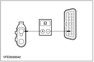
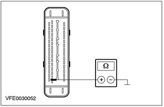
2 Measure the resistance between pin 1 of the C199 xenon headlight diagnostic connector, circuit 8-EE19A (white and black), and pin 7 of the C200 DLC connector, circuit 8-EE10 (white and black). |
|
• Is the resistance less than 2 ohms? |
|
|
→ Yes |
|
|
LOCATE and REPAIR open circuit 91-EE19 using the wiring diagrams (black and red) between Xenon headlight diagnostic connector and splice S118 (earth point G1). CHECK the system is working properly. |
|
|
→ No |
|
|
LOCATE and REPAIR open circuit 8-EE19A using the wiring diagrams (black and white) between Xenon headlight diagnostic connector and splice S140 (DLC). CHECK the system is working properly. |
|
|
H3: XENON HEADLIGHT CONTROL MODULE/ HEADLIGHT CORRECTION SENSOR VOLTAGE CHECK |
|
|
1 Enter the OFF position. |
|
|
2 Disconnect the C838 xenon headlight control module/headlight range sensor. |
|
|
3 Drive the ON position. |
|
|
4 Measure the voltage on the circuit between pin 2 of connector C838 of the xenon headlight control module/headlight range adjustment sensor, circuit 15-XL28C (green-orange), from the wiring side, and "ground". |
|
• Does the battery voltage register? |
|
|
→ Yes |
|
|
Move to H4 |
|
|
→ No |
|
|
LOCATE and REPAIR open circuit 15-XL28C using the wiring diagrams (green-orange) between splice S114 (fuse F53) and xenon headlight control module/headlight range correction sensor. CHECK the system is working properly. |
|
|
H4: XENON HEADLIGHT CONTROL MODULE/ HEADLIGHT CORRECTION SENSOR ELECTRICAL CHECK |
|
|
1 Enter the OFF position. |
|
|
2 Measure the resistance between C838 pin 1 of the xenon headlight control module/headlight range adjustment sensor, circuit 91-XL31 (black and blue), from the wiring side, and "ground". |
|
• Is the resistance less than 2 ohms? |
|
|
→ Yes |
|
|
Move to H5 |
|
|
→ No |
|
|
LOCATE and REPAIR open circuit 91-XL31 using the wiring diagrams (black and blue) between xenon headlight control module/headlight range correction sensor and splice S118 (earth point G1). CHECK the system is working properly. |
|
|
H5: CHECK THE ELECTRICAL CIRCUIT BETWEEN THE XENON HEADLIGHT CONTROL MODULE/ HEADLIGHT CORRECTION SENSOR AND DLC FOR AN OPEN |
|
|
1 Measure the resistance between pin 5 of connector C838 of the xenon headlight control module/headlight range adjustment sensor, circuit 8-EE19 (white and black), on the wiring side, and pin 7 of the C200 DLC plug connector, electrical circuit 8-EE10 (white and black). |
|
• Is the resistance less than 2 ohms? |
|
|
→ Yes |
|
|
INSPECT xenon headlight control module/headlight range sensor, INSTALL a new one if necessary. CHECK the system is working properly. |
|
|
→ No |
|
|
LOCATE and REPAIR open circuit 8-EE19 using the wiring diagrams (black and white) between xenon headlight control module/headlight range correction sensor and splice S140 (DLC). CHECK the system is working properly. |
|
PINPOINT TEST I: ELECTRONIC AUTOMATIC TEMPERATURE CONTROL (EATC) DOES NOT RESPOND TO DIAGNOSTIC TOOL QUERY (CHANNEL K ISO 9141, BUS SCP)
|
STATES |
DETAILS/RESULTS/ACTIONS |
|
I1: CHECK FUSE F45 |
|
|
1 Enter the OFF position. |
|
|
2CHECK Fuse F45 (CJB). |
|
|
• Is the fuse good? |
|
|
→ Yes |
|
|
Go to I2 |
|
|
→ No |
|
|
Install new fuse F45 (7.5 A). If the fuse blows again, LOCATE and REPAIR the short circuit using the wiring diagrams. CHECK the system is working properly. |
|
|
I2: FUSE VOLTAGE TEST F45 |
|
|
1 Connect Fuse F45 (CJB). |
|
|
2 Drive the ON position. |
|
|
3 Measure voltage between fuse F45 (7.5 A) and "mass". |
|
|
• Does the battery voltage register? |
|
|
→ Yes |
|
|
Go to I3 |
|
|
→ No |
|
|
Using the wiring diagrams, RESTORE power to fuse F45. If necessary, INSTALL a new CJB. CHECK the system is working properly. |
|
|
I3: SYSTEM CHECK USING WDS. |
|
|
1 Enter the OFF position. |
|
|
2 Connect the diagnostic tool. |
|
|
3 Check the system using WDS. |
|
|
• Are any DTCs logged? (DTC). |
|
|
→ Yes |
|
|
Take appropriate action on DTCs as directed by WDS. CLEAR fault memory and CHECK system for correct operation. |
|
|
→ No |
|
|
No response to scan tool request (Channel K ISO 9141): Go to I4 |
|
|
No module/communication with modules (SCP bus): Go to I9 |
|
|
I4: VOLTAGE TEST IN THE ELECTRONIC AUTOMATIC TEMPERATURE CONTROL UNIT (EATC) (WHEN THE IGNITION IS OFF) |
|
|
1 Enter the OFF position. |
|
|
2 Disconnect the C380 of the EATC module. |
|
|
3 Measure the voltage between pin 8 of connector C380 of the EATC module, circuit 29-FA13 (orange), from the wiring side, and "ground". |
|
• Does the battery voltage register? |
|
|
→ Yes |
|
|
Go to I5 |
|
|
→ No |
|
|
LOCATE and REPAIR open circuit 29-FA13 (orange) between splice S49 (fuse F36) and the EATC module using the wiring diagrams. CHECK the system is working properly. |
|
|
I5: CHECK THE VOLTAGE IN THE ELECTRICAL CIRCUIT OF THE EATC MODULE (WHEN THE IGNITION IS ON) |
|
|
1 Drive the ON position. |
|
|
2 Measure the voltage between pin 10 of connector C380 of the EATC module, circuit 15-FA13 (green-red), from the wiring side, and "ground". |
|
• Does the battery voltage register? |
|
|
→ Yes |
|
|
Go to I6 |
|
|
→ No |
|
|
LOCATE and REPAIR open circuit between fuse F45 (CJB) and the EATC module using the wiring diagrams. If necessary, INSTALL a new CJB. CHECK the system is working properly. |
|
|
I6: CHECK EATC MODULE GROUND CIRCUIT |
|
|
1 Enter the OFF position. |
|
|
2 Measure the resistance between pin 12 of connector C380 of the EATC module, circuit 91-FA13 (black-orange), from the wiring side, and "ground". |
|
• Is the resistance less than 2 ohms? |
|
|
→ Yes |
|
|
Go to I7 |
|
|
→ No |
|
|
LOCATE and REPAIR open circuit 91-FA13 (black-orange) between EATC module and splice S12 (earthing point G41), using wiring diagrams. CHECK the system is working properly. |
|
|
I7: CHECK THE VOLTAGE IN THE ELECTRICAL CIRCUIT OF THE EATC MODULE (ENGINE RUNNING) |
|
|
1 Drive the START position. |
|
|
2 Measure the voltage between pin 11 of connector C380 of the EATC module, circuit 64-HB6 (A) (blue), from the wiring side, and "ground". |
|
• Does the battery voltage register? |
|
|
→ Yes |
|
|
Go to I8 |
|
|
→ No |
|
|
LOCATE and REPAIR open circuit 64-HB6 (A) between engine running relays (BJB) and the EATC module using the wiring diagrams. CHECK the system is working properly. |
|
|
I8: 8-EE3 ELECTRICAL CIRCUIT CHECK (WHITE-RED) (CHANNEL K ISO 9141) BETWEEN EATC MODULE AND COMMUNICATION PLUG CONNECTOR (DLC) FOR A BREAK |
|
|
1 Enter the OFF position. |
|
|
2 Disconnect the C539 of the EATC module. |
|
|
3 Measure the resistance between pin 23 of connector C539 of the EATC module, circuit 8-EE3 (white-red), on the wiring side, and pin 7 of the C200 DLC plug connector, electrical circuit 8-EE10 (white and black). |
|
• Is the resistance less than 2 ohms? |
|
|
→ Yes |
|
|
CHECK the EATC module, INSTALL a new module if necessary. CHECK the system is working properly. |
|
|
→ No |
|
|
LOCATE and REPAIR open circuit 8-EE3 (white-red) between EATC module and splice S10 (DLC), using wiring diagrams. CHECK the system is working properly. |
|
|
I9: 4-EG1 ELECTRICAL CIRCUIT CHECK (GRAY-RED) (BUS SCP) BETWEEN ELECTRONIC AUTOMATIC TEMPERATURE CONTROL (EATC) AND COMMUNICATION PLUG CONNECTOR (DLC) FOR A BREAK |
|
|
1 Enter the OFF position. |
|
|
2 Disconnect the C539 of the EATC module. |
|
|
3 Measure the resistance between pin 22 of connector C539 of the EATC module, circuit 4-EG1 (grey-red), on the wiring side, and pin 2 of the C200 DLC plug connector, electrical circuit 4-EG7 (grey-red). |
|
• Is the resistance less than 2 ohms? |
|
|
→ Yes |
|
|
Go to I10 |
|
|
→ No |
|
|
LOCATE and REPAIR open circuit 4-EG1 (grey-red) between EATC module and splice S16 (DLC), using wiring diagrams. CHECK the system is working properly. |
|
|
I10: 5-EG1 ELECTRICAL CIRCUIT CHECK (RED-BLUE) (BUS SCP) FOR A BREAK BETWEEN EATC AND DLC |
|
|
1 Measure the resistance between pin 6 of connector C539 of the EATC module, circuit 5-EG1 (red-blue), on the wiring side, and pin 10 of the C200 DLC plug connector, electrical circuit 5-EG7 (red-blue). |
|
• Is the resistance less than 2 ohms? |
|
|
→ Yes |
|
|
CHECK the EATC module, INSTALL a new one if necessary. Check the correct operation of the system. |
|
|
→ No |
|
|
LOCATE and REPAIR open circuit 5-EG1 (red-blue) between EATC module and splice S17 (DLC), using wiring diagrams. CHECK the system is working properly. |
|
PINPOINT TEST J: ABS MODULE AND RESPECTIVE COURSE ELECTRONIC STABILITY PROGRAM MODULE (ESP) DOES NOT RESPOND TO DIAGNOSTIC TOOL QUERY (CHANNEL K ISO 9141, BUS SCP)
|
STATES |
DETAILS/RESULTS/ACTIONS |
|
J1: FUSE CHECK F21 |
|
|
1 Enter the OFF position. |
|
|
2CHECK Fuse F21 (BJB). |
|
|
• Is the fuse OK? |
|
|
→ Yes |
|
|
Go to J2 |
|
|
→ No |
|
|
Install new fuse F21 (20 A). If the fuse blows again, LOCATE and REPAIR the short circuit using the wiring diagrams. CHECK the system is working properly. |
|
|
J2: VOLTAGE CHECK ON FUSE AREA F21 |
|
|
1 Connect Fuse F21 (BJB). |
|
|
2 Drive the ON position. |
|
|
3 Measure voltage between fuse F21 (20 A) and "mass". |
|
|
• Does the battery voltage register? |
|
|
→ Yes |
|
|
Go to J3 |
|
|
→ No |
|
|
Using the wiring diagrams, RESTORE power to fuse F21. If necessary, INSTALL a new BJB. CHECK the system is working properly. |
|
|
J3: F11 FUSE CHECK |
|
|
1 Enter the OFF position. |
|
|
2CHECK Fuse F11 (BJB). |
|
|
• Is the fuse OK? |
|
|
→ Yes |
|
|
Go to J4 |
|
|
→ No |
|
|
Install new fuse F11 (30 A). If the fuse blows again, LOCATE and REPAIR the short circuit using the wiring diagrams. CHECK the system is working properly. |
|
|
J4: VOLTAGE CHECK IN FUSE AREA F11 |
|
|
1 Connect Fuse F11 (BJB). |
|
|
2 Drive the ON position. |
|
|
3 Measure voltage between fuse F11 (30 A) and "mass". |
|
|
• Does the battery voltage register? |
|
|
→ Yes |
|
|
Go to J5 |
|
|
→ No |
|
|
Using the wiring diagrams, RESTORE power to fuse F11. If necessary, INSTALL a new BJB. CHECK the system is working properly. |
|
|
J5: F46 FUSE CHECK |
|
|
1 Enter the OFF position. |
|
|
2 CHECK Fuse F46 (CJB). |
|
|
• Is the fuse good? |
|
|
→ Yes |
|
|
Go to J6 |
|
|
→ No |
|
|
Install new fuse F46 (7.5 A). If the fuse blows again, LOCATE and REPAIR the short circuit using the wiring diagrams. CHECK the system is working properly. |
|
|
J6: VOLTAGE CHECK IN FUSE AREA F46 |
|
|
1 Connect Fuse F46 (CJB). |
|
|
2 Drive the ON position. |
|
|
3 Measure voltage between fuse F46 (7.5 A) and "mass". |
|
|
• Does the battery voltage register? |
|
|
→ Yes |
|
|
Go to J7 |
|
|
→ No |
|
|
Using the wiring diagrams, RESTORE power to fuse F46. If necessary, INSTALL a new CJB. CHECK the system is working properly. |
|
|
J7: SYSTEM CHECK USING WDS. |
|
|
1 Enter the OFF position. |
|
|
2 Connect the diagnostic tool. |
|
|
3 Check the system using WDS. |
|
|
• Are any DTCs logged? (DTC). |
|
|
→ Yes |
|
|
Take appropriate action on DTCs as directed by WDS. CLEAR fault memory and CHECK system for correct operation. |
|
|
→ No |
|
|
No response to scan tool request (Channel K ISO 9141): Go to J8 |
|
|
No module/communication with modules (SCP bus): Go to J14 |
|
|
J8: VOLTAGE CHECK IN THE ABS MODULE AND THE RESPECTIVE ELECTRONIC STABILITY PROGRAM MODULE ON THE COURSE (ESP) |
|
|
1 Enter the OFF position. |
|
|
2 Disconnect the C 840 of the ABS module and respectively the ESP module. |
|
|
3 Measure the voltage between pin 32 of connector C840 of the ABS module and respectively of the ESP module, circuit 30-CF6A (red), from the wiring side, and "ground". |
|
• Does the battery voltage register? |
|
|
→ Yes |
|
|
Go to J9 |
|
|
→ No |
|
|
LOCATE and REPAIR open circuit 30-CF6A (red) between fuse F21 (BJB) and the ABS module and respectively the ESP module, using the wiring diagrams. CHECK the system is working properly. |
|
|
J9: CHECKING THE VOLTAGE IN THE ELECTRICAL CIRCUIT OF THE ABS MODULE AND RESPECTIVELY THE ESP MODULE |
|
|
1 Measure the voltage between pin 1 of the ABS module connector C840 and respectively the ESP module, circuit 30-CF13A (red), from the wiring side, and "ground". |
|
• Does the battery voltage register? |
|
|
→ Yes |
|
|
Go to J10 |
|
|
→ No |
|
|
LOCATE and REPAIR open circuit 30-CF13A (red) between fuse F11 (BJB) and the ABS module and respectively the ESP module, using the wiring diagrams. CHECK the system is working properly. |
|
|
J10: CHECKING THE VOLTAGE IN THE ELECTRICAL CIRCUIT OF THE ABS MODULE AND RESPECTIVELY THE ESP MODULE |
|
|
1 Drive the ON position. |
|
|
2 Measure the voltage between pin 4 of the ABS module connector C840 and respectively the ESP module, circuit 15-CF6A (green-yellow), from the wiring side, and "ground". |
|
• Does the battery voltage register? |
|
|
→ Yes |
|
|
Go to J11 |
|
|
→ No |
|
|
LOCATE and REPAIR open circuit between fuse F46 (CJB) and the ABS module and respectively the ESP module, using the wiring diagrams. If necessary, INSTALL a new CJB. CHECK the system is working properly. |
|
|
J11: CHECK THE GROUND ELECTRICAL CIRCUIT OF THE ABS MODULE AND RESPECTIVELY THE ESP MODULE |
|
|
1 Enter the OFF position. |
|
|
2 Measure the resistance between pin 16 of connector C840 of the ABS module and respectively of the ESP module, circuit 91-CF6 (black and yellow), from the wiring side, and "ground". |
|
• Is the resistance less than 2 ohms? |
|
|
→ Yes |
|
|
Go to J12 |
|
|
→ No |
|
|
LOCATE and REPAIR open circuit 91-CF6 (black and yellow) between ABS module and respectively ESP module and splice S141 (grounding point G55), using wiring diagrams. CHECK the system is working properly. |
|
|
J12: CHECK THE GROUND ELECTRICAL CIRCUIT OF THE ABS MODULE AND RESPECTIVELY THE ESP MODULE |
|
|
1 Measure the resistance between pin 47 of connector C840 of the ABS module and respectively of the ESP module, circuit 91-CF13 (black and blue), from the wiring side, and "ground". |
|
• Is the resistance less than 2 ohms? |
|
|
→ Yes |
|
|
Go to J13 |
|
|
→ No |
|
|
LOCATE and REPAIR open circuit 91-CF13 (black and blue) between ABS module and respectively ESP module and splice S141 (grounding point G55), using wiring diagrams. CHECK the system is working properly. |
|
|
J13: 8-EE6 ELECTRICAL CIRCUIT CHECK (A) (WHITE) (CHANNEL K ISO 9141) BETWEEN ABS MODULE AND RESPECTIVELY ESP MODULE AND COMMUNICATION PLUG CONNECTOR (DLC) FOR A BREAK |
|
|
1 Measure the resistance between pin 2 of connector C840 of the ABS module and respectively of the ESP module, circuit 8-EE6 (A) (white), on the wiring side, and pin 7 of the C200 DLC plug connector, electrical circuit 8-EE10 (white and black). |
|
• Is the resistance less than 2 ohms? |
|
|
→ Yes |
|
|
CHECK the ABS module and respectively the ESP module, INSTALL a new one if necessary. CHECK the system is working properly. |
|
|
→ No |
|
|
LOCATE and REPAIR open circuit 8-EE6 (A) (white) between the ABS module and respectively the ESP module and splice S140 (DLC), using wiring diagrams. CHECK the system is working properly. |
|
|
J14: 4-EG6 ELECTRICAL CIRCUIT CHECK (GRAY) (BUS SCP) BETWEEN ABS MODULE AND RESPECTIVE ELECTRONIC STABILITY PROGRAM MODULE ON COURSE (ESP) AND COMMUNICATION PLUG CONNECTOR (DLC) FOR A BREAK |
|
|
1 Enter the OFF position. |
|
|
2 Disconnect the C840 ABS module and ESP module respectively. |
|
|
3 Measure the resistance between pin 12 of connector C840 of the ABS module and respectively of the ESP module, circuit 4-EG6 (gray), on the wiring side, and pin 2 of the C200 DLC plug connector, electrical circuit 4-EG7 (grey-red). |
|
• Is the resistance less than 2 ohms? |
|
|
→ Yes |
|
|
Go to J15 |
|
|
→ No |
|
|
LOCATE and REPAIR open circuit 4-EG6 (gray) between the ABS module and respectively the ESP module and splice S16 (DLC), using wiring diagrams. CHECK the system is working properly. |
|
|
J15: 5-EG7 ELECTRICAL CIRCUIT CHECK (BLUE) (BUS SCP) BETWEEN THE ABS MODULE AND, RESPECTIVELY, THE ESP AND DLC MODULE FOR THE PRESENCE OF A GAP |
|
|
1 Measure the resistance between pin 14 of connector C840 of the ABS module and respectively of the ESP module, circuit 5-EG6 (blue), on the wiring side, and C200 DLC plug connector, pin 10, electrical circuit 5-EG7 (red-blue). |
|
• Is the resistance less than 2 ohms? |
|
|
→ Yes |
|
|
CHECK the ABS module and respectively the ESP module, INSTALL a new one if necessary. CHECK the system is working properly. |
|
|
→ No |
|
|
LOCATE and REPAIR open circuit 5-EG6 (blue) between the ABS module and respectively the ESP module and splice S17 (DLC), using wiring diagrams. CHECK the system is working properly. |
|
PINPOINT TEST K: AUXILIARY HEATER DOES NOT RESPOND TO TEST TOOL (CHANNEL K ISO 9141)
|
STATES |
DETAILS/RESULTS/ACTIONS |
|
K1: FUSE CHECK F23 |
|
|
1 Enter the OFF position. |
|
|
2 CHECK Fuse F23 (BJB). |
|
|
• Is the fuse OK? |
|
|
→ Yes |
|
|
Go to K2 |
|
|
→ No |
|
|
Install new fuse F23 (20 A). If the fuse blows again, LOCATE and REPAIR the short circuit using the wiring diagrams. CHECK the system is working properly. |
|
|
K2: FUSE VOLTAGE CHECK F23 |
|
|
1 Connect Fuse F23 (BJB). |
|
|
2 Measure voltage between fuse F23 (20 A) and "mass". |
|
|
• Does the battery voltage register? |
|
|
→ Yes |
|
|
Go to K3 |
|
|
→ No |
|
|
Using the wiring diagrams, RESTORE power to fuse F23. If necessary, INSTALL a new BJB. CHECK the system is working properly. |
|
|
K3: SYSTEM CHECK USING WDS. |
|
|
1 Enter the OFF position. |
|
|
2 Connect the diagnostic tool. |
|
|
3 Check the system using WDS. |
|
|
• Are any DTCs logged? (DTC). |
|
|
→ Yes |
|
|
Take appropriate action on DTCs as directed by WDS. CLEAR fault memory and CHECK system for correct operation. |
|
|
→ No |
|
|
Go to K4 |
|
|
K4: AUXILIARY HEATER VOLTAGE CHECK (IGNITION OFF) |
|
|
1 Enter the OFF position. |
|
|
2 Disconnect the C878 auxiliary heater. |
|
|
3 Measure the voltage on the circuit between pin 1 of the auxiliary heater connector C878, circuit 30-RD18 (red), from the wiring side, and "ground". |
|
• Does the battery voltage register? |
|
|
→ Yes |
|
|
Go to K5 |
|
|
→ No |
|
|
LOCATE and REPAIR open circuit 30-RD18 using the wiring diagrams (red) between fuse F23 (BJB) and additional heater. CHECK the system is working properly. |
|
|
K5: AUXILIARY HEATER VOLTAGE CHECK (IGNITION ON) |
|
|
1 Drive the ON position. |
|
|
2 Measure the voltage on the circuit between pin 4 of the auxiliary heater connector C878, circuit 15-RD18 (red-green), from the wiring side, and "ground". |
|
• Does the battery voltage register? |
|
|
→ Yes |
|
|
Go to K6 |
|
|
→ No |
|
|
LOCATE and REPAIR open circuit 15-RD18 using the wiring diagrams (red-green) between splice S117 (power supply relay) and additional heater. CHECK the system is working properly. |
|
|
K6: AUXILIARY HEATER GROUND CIRCUIT CHECK |
|
|
1 Enter the OFF position. |
|
|
2 Measure the resistance between pin 2 of auxiliary heater connector C878, circuit 31-RD18 (black), from the wiring side, and "ground". |
|
• Is the resistance less than 2 ohms? |
|
|
→ Yes |
|
|
Go to K7 |
|
|
→ No |
|
|
LOCATE and REPAIR open circuit 31-RD18 using the wiring diagrams (black) between auxiliary heater and splice S121 (grounding point G37). CHECK the system is working properly. |
|
|
K7: CHECK THE ELECTRICAL CIRCUIT BETWEEN AUXILIARY HEATER AND COMMUNICATION PLUG (DLC) FOR A BREAK |
|
|
1 Measure the resistance between pin 3 of the auxiliary heater connector C878, circuit 8-EE11 (white-violet), on the wiring side, and pin 7 of the C200 DLC plug connector, electrical circuit 8-EE10 (white and black), from the side of the electrical wiring. |
|
• Is the resistance less than 2 ohms? |
|
|
→ Yes |
|
|
CHECK the auxiliary heater, INSTALL a new one if necessary. CHECK the system is working properly. |
|
|
→ No |
|
|
LOCATE and REPAIR open circuit 8-EE11 using the wiring diagrams (white-violet) between auxiliary heater and splice S140 (DLC). CHECK the system is working properly. |
|
PINPOINT TEST L: GENERAL ELECTRONIC MODULE (GEM) DOES NOT RESPOND TO DIAGNOSTIC TOOL QUERY (CHANNEL K ISO 9141)
|
STATES |
DETAILS/RESULTS/ACTIONS |
|
L1: FUSE CHECK F63 |
|
|
1 Enter the OFF position. |
|
|
2 CHECK Fuse F63 (CJB). |
|
|
• Is the fuse good? |
|
|
→ Yes |
|
|
Go to L2 |
|
|
→ No |
|
|
Install new fuse F63 (20 A). If the fuse blows again, LOCATE and REPAIR the short circuit using the wiring diagrams. CHECK the system is working properly. |
|
|
L2: CHECK THE VOLTAGE IN THE FUSE AREA F63 |
|
|
1 Connect F63 Fuse (CJB). |
|
|
2 Measure voltage between fuse F63 (20 A) and "mass". |
|
|
• Does the battery voltage register? |
|
|
→ Yes |
|
|
Go to L3 |
|
|
→ No |
|
|
Using the wiring diagrams, RESTORE power to fuse F63. If necessary, INSTALL a new CJB. CHECK the system is working properly. |
|
|
L3: FUSE CHECK F32 |
|
|
1 Enter the OFF position. |
|
|
2CHECK Fuse F32 (CJB). |
|
|
• Is the fuse good? |
|
|
→ Yes |
|
|
Go to L4 |
|
|
→ No |
|
|
Install new fuse F32 (15 A). If the fuse blows again, LOCATE and REPAIR the short circuit using the wiring diagrams. CHECK the system is working properly. |
|
|
L4: VOLTAGE CHECK OF THE FUSE AREA F32 |
|
|
1 Connect Fuse F32 (CJB). |
|
|
2 Measure voltage between fuse F32 (15 A) and "mass". |
|
|
• Does the battery voltage register? |
|
|
→ Yes |
|
|
Go to L5 |
|
|
→ No |
|
|
Using the wiring diagrams, RESTORE power to fuse F32. If necessary, INSTALL a new CJB. CHECK the system is working properly. |
|
|
L5: SYSTEM CHECK USING WDS. |
|
|
1 Enter the OFF position. |
|
|
2 Connect the diagnostic tool. |
|
|
3 Check the system using WDS. |
|
|
• Are any DTCs logged? (DTC). |
|
|
→ Yes |
|
|
Take appropriate action on DTCs as directed by WDS. CLEAR fault memory and CHECK system for correct operation. |
|
|
→ No |
|
|
Go to L6 |
|
|
L6: VOLTAGE CHECK IN THE ELECTRICAL CIRCUIT OF THE COMMON ELECTRONIC MODULE (GEM) |
|
|
1 Enter the OFF position. |
|
|
2 Disconnect C103 GEM. |
|
|
3 Drive the ON position. |
|
|
4 Measure the voltage between pin 1 of the C103 GEM connector, circuit 29-AA17 (orange white), from the wiring side, and "ground". |
|
• Does the battery voltage register? |
|
|
→ Yes |
|
|
Go to L7 |
|
|
→ No |
|
|
LOCATE and REPAIR open circuit between fuse F63 (CJB) and GEM using wiring diagrams. If necessary, INSTALL a new CJB. CHECK the system is working properly. |
|
|
L7: GEM VOLTAGE CHECK |
|
|
1 Measure the voltage between GEM pin 5 of plug connector C103, circuit 29-DK20 (orange green), from the wiring side, and "ground". |
|
• Does the battery voltage register? |
|
|
→ Yes |
|
|
Go to L8 |
|
|
→ No |
|
|
LOCATE and REPAIR open circuit between fuse F32 (CJB) and GEM using wiring diagrams. If necessary, INSTALL a new CJB. CHECK the system is working properly. |
|
|
L8: GEM VOLTAGE CHECK (WHEN THE KEY IS IN THE IGNITION SWITCH) |
|
|
NOTE: The key must be inserted into the ignition switch |
|
|
1 Enter the OFF position. |
|
|
2 Disconnect C104 GEM. |
|
|
3 Measure the voltage between pin 8 of the C104 GEM connector, circuit 30S-TA31A (red-black), from the wiring side, and "ground". |
|
• Does the battery voltage register? |
|
|
→ Yes |
|
|
Go to L10 |
|
|
→ No |
|
|
Go to L9 |
|
|
L9: IGNITION SWITCH CHECK |
|
|
1 Check the ignition switch as described in chap. "Checking the elements", attached to the wiring diagrams. |
|
|
• Is the ignition switch OK? |
|
|
→ Yes |
|
|
LOCATE and REPAIR open circuit 30S-TA31 (A) (red-black) between the ignition switch and the GEM using the wiring diagrams. CHECK the system is working properly. |
|
|
→ No |
|
|
For more information, please refer to the relevant chapter. CHECK the system is working properly. |
|
|
L10: GEM GROUND CHECK |
|
|
1 Measure the resistance between pin 1 of the C104 GEM connector, circuit 91-DK20 (black and red), from the wiring side, and "ground". |
|
• Is the resistance less than 2 ohms? |
|
|
→ Yes |
|
|
Go to L11 |
|
|
→ No |
|
|
LOCATE and REPAIR open circuit 91-DK20 (black and red) between GEM and splice S12 (earthing point G41), using wiring diagrams. CHECK the system is working properly. |
|
|
L11: GEM GROUND CHECK |
|
|
1 Disconnect C101 GEM. |
|
|
2 Measure the resistance between pin 5 of the C101 GEM connector, circuit 31-DK20 (black), from the wiring side, and "ground". |
|
• Is the resistance less than 2 ohms? |
|
|
→ Yes |
|
|
Go to L12 |
|
|
→ No |
|
|
LOCATE and REPAIR open circuit 31-DK20 (black) between GEM and earth point G53 using the wiring diagrams. CHECK the system is working properly. |
|
|
L12: 8-EE9 ELECTRICAL CIRCUIT CHECK (WHITE-GREEN) BETWEEN GEM AND COMMUNICATION PLUG CONNECTOR (DLC) FOR A BREAK |
|
|
1 Measure the resistance between pin 16 of the C104 GEM connector, circuit 8-EE9 (white-green), on the wiring side, and pin 7 of the C200 DLC plug connector, electrical circuit 8-EE10 (white and black). |
|
• Is the resistance less than 2 ohms? |
|
|
→ Yes |
|
|
CHECK GEM, if necessary INSTALL a new one. CHECK the system is working properly. |
|
|
→ No |
|
|
LOCATE and REPAIR open circuit 8-EE9 (white-green) between GEM and splice S10 (DLC), using wiring diagrams. CHECK the system is working properly. |
|
PINPOINT TEST M: TRIP COMPUTER UNIT DOES NOT RESPOND TO TEST TOOL (CHANNEL K ISO 9141)
|
STATES |
DETAILS/RESULTS/ACTIONS |
|
M1: F61 FUSE CHECK |
|
|
1 Enter the OFF position. |
|
|
2CHECK Fuse F61 (CJB). |
|
|
• Is the fuse good? |
|
|
→ Yes |
|
|
Navigate to M2 |
|
|
→ No |
|
|
Install new fuse F61 (7.5 A). If the fuse blows again, LOCATE and REPAIR the short circuit using the wiring diagrams. CHECK the system is working properly. |
|
|
M2: VOLTAGE CHECK OF THE FUSE AREA F61 |
|
|
1 Connect Fuse F61 (CJB). |
|
|
2 Drive the ON position. |
|
|
3 Measure voltage between fuse F61 (7.5 A) and "mass". |
|
|
• Does the battery voltage register? |
|
|
→ Yes |
|
|
Go to M3 |
|
|
→ No |
|
|
Using the wiring diagrams, RESTORE power to fuse F61. If necessary, INSTALL a new CJB. CHECK the system is working properly. |
|
|
M3: FUSE CHECK F36 |
|
|
1 Enter the OFF position. |
|
|
2 CHECK Fuse F36 (CJB). |
|
|
• Is the fuse good? |
|
|
→ Yes |
|
|
Go to M4 |
|
|
→ No |
|
|
Install new fuse F36 (7.5 A). If the fuse blows again, LOCATE and REPAIR the short circuit using the wiring diagrams. CHECK the system is working properly. |
|
|
M4: FUSE VOLTAGE TEST F36 |
|
|
1 Connect Fuse F36 (CJB). |
|
|
2 Measure voltage between fuse F36 (7.5 A) and "mass". |
|
|
• Does the battery voltage register? |
|
|
→ Yes |
|
|
Go to M5 |
|
|
→ No |
|
|
Using the wiring diagrams, RESTORE power to fuse F36. If necessary, INSTALL a new CJB. CHECK the system is working properly. |
|
|
M5: SYSTEM CHECK USING WDS. |
|
|
1 Enter the OFF position. |
|
|
2 Connect the diagnostic tool. |
|
|
3 Check the system using WDS. |
|
|
• Are any DTCs logged? (DTC). |
|
|
→ Yes |
|
|
Take appropriate action on DTCs as directed by WDS. CLEAR fault memory and CHECK system for correct operation. |
|
|
→ No |
|
|
Go to M6 |
|
|
M6: TRIP COMPUTER MODULE ELECTRICAL VOLTAGE TEST (IGNITION ON) |
|
|
1 Enter the OFF position. |
|
|
2 Disconnect the trip computer module C467. |
|
|
3 Drive the ON position. |
|
|
4 Measure the voltage on the circuit between pin 18 of trip computer module connector C467, circuit 15-GE6 (yellow-green), from the wiring side, and "ground". |
|
• Does the battery voltage register? |
|
|
→ Yes |
|
|
Go to M7 |
|
|
→ No |
|
|
Using the wiring diagrams, LOCATE and REPAIR the open circuit between fuse F61 (CJB) and trip computer module. If necessary, INSTALL a new CJB. CHECK the system is working properly. |
|
|
M7: TRIP COMPUTER MODULE ELECTRICAL VOLTAGE TEST (IGNITION OFF) |
|
|
1 Enter the OFF position. |
|
|
2 Measure the voltage on the circuit between pin 17 of trip computer module connector C467, circuit 29-GE6 (yellow-orange), from the wiring side, and "ground". |
|
• Does the battery voltage register? |
|
|
→ Yes |
|
|
Go to M8 |
|
|
→ No |
|
|
Using the wiring diagrams, LOCATE and REPAIR the open circuit between fuse F36 (CJB) and trip computer module. If necessary, INSTALL a new CJB. CHECK the system is working properly. |
|
|
M8: TRIP COMPUTER UNIT GROUND ELECTRICAL CHECK |
|
|
1 Measure the resistance between pin 20 of trip computer module connector C467, circuit 91-GE6 (black and yellow), from the wiring side, and "ground". |
|
• Is the resistance less than 2 ohms? |
|
|
→ Yes |
|
|
Go to M9 |
|
|
→ No |
|
|
LOCATE and REPAIR open circuit 91-GE6 using the wiring diagrams (black and yellow) between trip computer module and splice S12 (earthing point G41). CHECK the system is working properly. |
|
|
M9: CHECK THE ELECTRICAL CIRCUIT BETWEEN ROUTE COMPUTER MODULE AND COMMUNICATION PLUG CONNECTOR (DLC) FOR A BREAK |
|
|
1 Measure the resistance between pin 26 of trip computer module connector C467, circuit 8-EE12 (white), on the wiring side, and pin 7 of the C200 DLC plug connector, electrical circuit 8-EE10 (white and black), from the side of the electrical wiring. |
|
• Is the resistance less than 2 ohms? |
|
|
→ Yes |
|
|
CHECK the trip computer module, INSTALL a new one if necessary. CHECK the system is working properly. |
|
|
→ No |
|
|
LOCATE and REPAIR open circuit 8-EE12 using the wiring diagrams (white) between trip computer module and splice S10 (DLC). CHECK the system is working properly. |
|
PINPOINT TEST N: POWERTRAIN CONTROL MODULE (PCM) DOES NOT RESPOND TO DIAGNOSTIC TOOL QUERY (BUS SCP)
|
STATES |
DETAILS/RESULTS/ACTIONS |
|
N1: DETERMINING THE TYPE OF POWER PACK CONTROL UNIT (PCM) |
|
|
1 Check PCM type. |
|
|
• Is this a PCM with a 121-pin male connector? |
|
|
→ Yes |
|
|
Go to N26 |
|
|
→ No |
|
|
Go to N2 |
|
|
N2: FUSE CHECK F20 |
|
|
1 CHECK F20 fuse (BJB). |
|
|
• Is the fuse good? |
|
|
→ Yes |
|
|
Go to N3 |
|
|
→ No |
|
|
Install new fuse F20 (10 A). If the fuse blows again, LOCATE and REPAIR the short circuit using the wiring diagrams. CHECK the system is working properly. |
|
|
N3: CHECK THE VOLTAGE IN THE FUSE AREA F20 |
|
|
1 Connect F20 fuse (BJB). |
|
|
2 Measure voltage between fuse F20 (10 A) and "mass". |
|
|
• Does the battery voltage register? |
|
|
→ Yes |
|
|
Diesel engines Go to N4 |
|
|
Gasoline engines Go to N6 |
|
|
→ No |
|
|
Using the wiring diagrams, RESTORE power to fuse F20. If necessary, INSTALL a new BJB. CHECK the system is working properly. |
|
|
N4: FUSE CHECK F28 |
|
|
1 Enter the OFF position. |
|
|
2 CHECK Fuse F28 (BJB). |
|
|
• Is the fuse good? |
|
|
→ Yes |
|
|
Go to N5 |
|
|
→ No |
|
|
Install new fuse F28 (10 A). If the fuse blows again, LOCATE and REPAIR the short circuit using the wiring diagrams. CHECK the system is working properly. |
|
|
N5: FUSE VOLTAGE CHECK F28 |
|
|
1 Connect Fuse F28 (BJB). |
|
|
2 Drive the ON position. |
|
|
3 Measure voltage between fuse F28 (10 A) and "mass". |
|
|
• Does the battery voltage register? |
|
|
→ Yes |
|
|
Go to N6 |
|
|
→ No |
|
|
LOCATE and REPAIR open circuit 15-DC28 using the wiring diagrams (green-blue) between splice S119 (ignition switch) and fuse F28 (BJB). CHECK the system is working properly. |
|
|
N6: SYSTEM CHECK USING WDS. |
|
|
1 Enter the OFF position. |
|
|
2 Connect the diagnostic tool. |
|
|
3 Check the system using WDS. |
|
|
• Are any DTCs logged? (DTC). |
|
|
→ Yes |
|
|
Take appropriate action on DTCs as directed by WDS. CLEAR fault memory and CHECK system for correct operation. |
|
|
→ No |
|
|
Go to N7 |
|
|
N7: 4-EG9 ELECTRICAL CIRCUIT CHECK (GRAY ORANGE) FOR A BREAK |
|
|
1 Enter the OFF position. |
|
|
2 Disconnect C415 PCM (and respectively C416, 60-pin EEC V) powertrain control module (PCM). |
|
|
3 Disconnect the diagnostic tool. |
|

|
4 Measure the resistance between pin 16 of the C415 PCM connector (and respectively pin 19 C416), electrical circuit 4-EG9 (grey-orange), on the wiring side, and pin 2 of the C200 DLC connector, electrical circuit 4-EG7 (red-gray), from the side of the electrical wiring. |
|
• Is the resistance less than 2 ohms? |
|
|
→ Yes |
|
|
Go to N8 |
|
|
→ No |
|
|
LOCATE and REPAIR open circuit 4-EG9 using the wiring diagrams (grey-orange) between PCM and DLC. Check the correct operation of the system. |
|
|
N8: 5-EG9 ELECTRICAL CIRCUIT CHECK (BLACK-BLUE) FOR A BREAK |
|
|
1 Measure the resistance between pin 15 of the C415 PCM connector (and respectively pin 18 C416), electrical circuit 5-EG9 (black and blue), on the wiring side, and pin 10 of the C200 connector of the data link connector (DLC),, electrical circuit 5-EG7 (red-blue), from the side of the electrical wiring. |
|
• Is the resistance less than 2 ohms? |
|
|
→ Yes |
|
|
Go to N9 |
|
|
→ No |
|
|
LOCATE and REPAIR open circuit 5-EG9 using the wiring diagrams (black and blue) between PCM and DLC. CHECK the system is working properly. |
|
|
N9: PCM ELECTRICAL VOLTAGE CHECK (THROUGH FUSE F20) |
|
|
1 Drive the ON position. |
|
|
2 Measure the voltage in the electrical circuit between pin 55 of connector C415 (and respectively pin 1 C416) PCM, electrical circuit 30-RE8 (red), from the wiring side, and "ground". |
|
• Does the battery voltage register? |
|
|
→ Yes |
|
|
Diesel engines Go to N10 |
|
|
Gasoline engines with 60-pin EEC V: Go to N15 |
|
|
Gasoline engines with 104-pin EEC V: Go to N20 |
|
|
→ No |
|
|
LOCATE and REPAIR open circuit 30-RE8 using the wiring diagrams (red) between fuse F20 (BJB) and PCM. If necessary, INSTALL a new BJB. CHECK the system is working properly. |
|
|
N10: PCM ELECTRICAL VOLTAGE CHECK (VIA FUSE F28) |
|
|
1 Measure the voltage on the circuit between pin 8 of connector C415 PCM, circuit 15-RE17 (green-blue), from the wiring side, and "ground". |
|
• Does the battery voltage register? |
|
|
→ Yes |
|
|
Go to N11 |
|
|
→ No |
|
|
LOCATE and REPAIR open circuit 15-RE17 using the wiring diagrams (green-blue) between fuse F28 (BJB) and PCM. If necessary, INSTALL a new BJB. CHECK the system is working properly. |
|
|
N11: PCM ELECTRICAL VOLTAGE CHECK (THROUGH THE FUSE F9) |
|
|
1 Measure the voltage on the circuit between pin 97 of connector C415 PCM, circuit 15-RE8A (yellow-green), from the wiring side, and "ground". |
|
• Does the battery voltage register? |
|
|
→ Yes |
|
|
Go to N12 |
|
|
→ No |
|
|
LOCATE and REPAIR open circuit 15-RE8A using the wiring diagrams (yellow-green) between splice S54 and PCM. CHECK the system is working properly. |
|
|
N12: PCM GROUND CIRCUIT CHECK (VIA G1) |
|
|
1 Measure the resistance between pin 103, circuit 91-RE8C (black and yellow), and respectively pin 76 of the C415 PCM connector, electrical circuit 91-RE8E (black and yellow), from the wiring side, and "ground". |
|
• Is the resistance less than 2 ohms? |
|
|
→ Yes |
|
|
Go to N13 |
|
|
→ No |
|
|
Using the wiring diagrams, LOCATE and REPAIR the open in circuit 91-RE8C or 91-RE8E between splice S53 and ground point G1. CHECK the system is working properly. |
|
|
N13: PCM GROUND CIRCUIT CHECK (VIA G1) |
|

|
1 Measure the resistance between pin 77 of connector C415 PCM, circuit 91-RE8 (black and yellow), from the wiring side, and "ground". |
|
• Is the resistance less than 2 ohms? |
|
|
→ Yes |
|
|
Go to N14 |
|
|
→ No |
|
|
Using the wiring diagrams, LOCATE and REPAIR the open in circuit 91-RE8 between the PCM and ground point G1. CHECK the system is working properly. |
|
|
N14: PCM GROUND CIRCUIT CHECK (VIA G24) |
|
|
1 Measure the resistance between pin 25 of connector C415 PCM, circuit 31-RE8 (black), from the wiring side, and "ground". |
|
• Is the resistance less than 2 ohms? |
|
|
→ Yes |
|
|
CHECK PCM, INSTALL a new one if necessary. CHECK the system is working properly. |
|
|
→ No |
|
|
Using the wiring diagrams, LOCATE and REPAIR the open in circuit 31-RE8 between the PCM and ground point G24. CHECK the system is working properly. |
|
|
N15: PCM ELECTRICAL VOLTAGE CHECK (THROUGH THE FUSE F12) |
|
|
1 Measure the voltage on the circuit between pin 8 of connector C416 PCM, circuit 15-RE16 (black and green), from the wiring side, and "ground". |
|
• Does the battery voltage register? |
|
|
→ Yes |
|
|
Go to N16 |
|
|
→ No |
|
|
Using the wiring diagrams, LOCATE and REPAIR the open in circuit 15-RE16 between splice S60 and PCM. CHECK the system is working properly. |
|
|
N16: PCM ELECTRICAL VOLTAGE CHECK (THROUGH THE FUSE F9) |
|
|
1 Measure the voltage in the circuit between pin 37, circuit 15-RE8 (yellow-green), and, accordingly, pin 57, electrical circuit 15-RE8A (yellow-green), C416 PCM connector, wiring side, and ground. |
|
• Is the battery voltage recorded in both cases? |
|
|
→ Yes |
|
|
Go to N17 |
|
|
→ No |
|
|
Both measurements do not indicate battery voltage: using the wiring diagrams, LOCATE and REPAIR the open circuit between fuse F9 and splice S54. CHECK the system is working properly. |
|
|
One measurement does not indicate battery voltage: Using the wiring diagrams, LOCATE and REPAIR the open in circuit 15-RE8 or 15-RE8A between splice S54 and PCM. CHECK the system is working properly. |
|
|
N17: PCM GROUND CIRCUIT CHECK (VIA G1) |
|
|
1 Measure the resistance between pin 60, circuit 91-RE8B (black and yellow), and accordingly pin 40, electrical circuit 91-RE8A (black and yellow), C416 PCM connector, wiring side, and ground. |
|
• Is the 2 ohm resistance lower in both measurements? |
|
|
→ Yes |
|
|
Go to N18 |
|
|
→ No |
|
|
Both measurements show more than 2 ohms: using the wiring diagrams, LOCATE and REPAIR the open circuit between splice S53 and ground point G1. CHECK the system is working properly. |
|
|
One measurement shows more than 2 ohms: LOCATE and REPAIR the open in circuit 91-RE8B or 91-RE8A between splice S53 and ground point G1 using the wiring diagrams. CHECK the system is working properly. |
|
|
N18: PCM GROUND CIRCUIT CHECK (VIA G1) |
|
|
1 Measure the resistance between pin 16 of connector C416 PCM, circuit 91-RE8 (black and yellow), from the wiring side, and "ground". |
|
• Is the resistance less than 2 ohms? |
|
|
→ Yes |
|
|
Go to N19 |
|
|
→ No |
|
|
Using the wiring diagrams, LOCATE and REPAIR the open in circuit 91-RE8 between the PCM and ground point G1. CHECK the system is working properly. |
|
|
N19: PCM GROUND CIRCUIT CHECK (VIA G24) |
|
|
1 Measure the resistance between pin 20 of connector C416 PCM, circuit 31-RE8 (black), from the wiring side, and "ground". |
|
• Is the resistance less than 2 ohms? |
|
|
→ Yes |
|
|
CHECK PCM, INSTALL a new one if necessary. CHECK the system is working properly. |
|
|
→ No |
|
|
Using the wiring diagrams, LOCATE and REPAIR the open in circuit 31-RE8 between the PCM and ground point G24. CHECK the system is working properly. |
|
|
N20: PCM ELECTRICAL VOLTAGE CHECK (THROUGH THE FUSE F9) |
|
|
1 Measure the voltage in the circuit between pin 71, circuit 15-RE8 (yellow-green), and accordingly pin 97, electrical circuit 15-RE8A (yellow-green), C415 PCM connector, wiring side, and ground. |
|
• Is the battery voltage recorded in both cases? |
|
|
→ Yes |
|
|
Except DURATEC-ST: Go to N21 |
|
|
DURATEC-ST: Go to N22 |
|
|
→ No |
|
|
Both measurements do not indicate battery voltage: using the wiring diagrams, LOCATE and REPAIR the open circuit between fuse F9 and splice S54. CHECK the system is working properly. |
|
|
One measurement does not indicate battery voltage: Using the wiring diagrams, LOCATE and REPAIR the open in circuit 15-RE8 or 15-RE8A between splice S54 and PCM. CHECK the system is working properly. |
|
|
N21: PCM ELECTRICAL VOLTAGE CHECK (THROUGH THE FUSE F12) |
|
|
1 Measure the voltage on the circuit between pin 40 of connector C415 PCM, circuit 15-RE16 (black and green), from the wiring side, and "ground". |
|
• Does the battery voltage register? |
|
|
→ Yes |
|
|
Go to N22 |
|
|
→ No |
|
|
Using the wiring diagrams, LOCATE and REPAIR the open in circuit 15-RE16 between splice S60 and PCM. CHECK the system is working properly. |
|
|
N22: PCM GROUND CIRCUIT CHECK (VIA G1) |
|
|
1 Enter the OFF position. |
|
|
2 Measure the resistance between pin 103, circuit 91-RE8C (black and yellow), and, accordingly, pin 51, electrical circuit 91-RE8B (black and yellow), and accordingly pin 24, electrical circuit 91-RE8A (black and yellow), C415 PCM connector, wiring side, and ground. |
|
• Is the resistance less than 2 ohms for each measurement? |
|
|
→ Yes |
|
|
DURATEC-ST: Go to N23 |
|
|
Except DURATEC-ST: Go to N24 |
|
|
→ No |
|
|
One measurement shows more than 2 ohms: Using the wiring diagrams, LOCATE and REPAIR the open in circuit 91-RE8C, 91-RE8B, or 91-RE8A between PCM and splice S53. CHECK the system is working properly. |
|
|
All measurements show greater than 2 ohms: using the wiring diagrams, LOCATE and REPAIR the open circuit between splice S53 and ground point G1. CHECK the system is working properly. |
|
|
N23: PCM GROUND CIRCUIT CHECK (VIA G1) |
|

|
1 Measure the resistance between pin 23 of connector C415 PCM, circuit 91-RE8E (black and yellow), from the wiring side, and "ground". |
|
• Is the resistance less than 2 ohms? |
|
|
→ Yes |
|
|
Go to N24 |
|
|
→ No |
|
|
Using the wiring diagrams, LOCATE and REPAIR the open in circuit 91-RE8E between the PCM and splice S53. CHECK the system is working properly. |
|
|
N24: PCM GROUND CIRCUIT CHECK (VIA G1) |
|

|
1 Measure the resistance between pin 77 of connector C415 PCM, circuit 91-RE8 (black and yellow), from the wiring side, and "ground". |
|
• Is the resistance less than 2 ohms? |
|
|
→ Yes |
|
|
Go to N25 |
|
|
→ No |
|
|
LOCATE and REPAIR open circuit 91-RE8 using the wiring diagrams (black and yellow) between PCM and ground point G1. CHECK the system is working properly. |
|
|
N25: PCM GROUND CIRCUIT CHECK (VIA G24) |
|

|
1 Measure the resistance between pin 25 of connector C415 PCM, circuit 31-RE8 (black), from the wiring side, and "ground". |
|
• Is the resistance less than 2 ohms? |
|
|
→ Yes |
|
|
CHECK PCM, INSTALL a new one if necessary. CHECK the system is working properly. |
|
|
→ No |
|
|
Using the wiring diagrams, LOCATE and REPAIR the open in circuit 31-RE8 between the PCM and ground point G24. CHECK the system is working properly. |
|
|
N26: CHECK THE FUSE F9 |
|
|
1 Enter the OFF position. |
|
|
2CHECK Fuse F9 (BJB). |
|
|
• Is the fuse good? |
|
|
→ Yes |
|
|
Go to N27 |
|
|
→ No |
|
|
Install new fuse F9 (20 A). If the fuse blows again, LOCATE and REPAIR the short circuit using the wiring diagrams. CHECK the system is working properly. |
|
|
N27: CHECK THE VOLTAGE IN THE FUSE AREA F9 |
|
|
1 Connect Fuse F9 (BJB). |
|
|
2 Measure voltage between fuse F9 (20 A) and "mass". |
|
|
• Does the battery voltage register? |
|
|
→ Yes |
|
|
Go to N28 |
|
|
→ No |
|
|
Using the wiring diagrams, RESTORE power to fuse F9. CHECK the system is working properly. |
|
|
N28: FUSE CHECK F28 |
|
|
1 CHECK Fuse F28 (BJB). |
|
|
• Is the fuse good? |
|
|
→ Yes |
|
|
Go to N29 |
|
|
→ No |
|
|
Install new fuse F28 (10 A). If the fuse blows again, LOCATE and REPAIR the short circuit using the wiring diagrams. CHECK the system is working properly. |
|
|
N29: FUSE VOLTAGE CHECK F28 |
|
|
1 Connect Fuse F28 (BJB). |
|
|
2 Drive the ON position. |
|
|
3 Measure voltage between fuse F28 (10 A) and "mass". |
|
|
• Does the battery voltage register? |
|
|
→ Yes |
|
|
Go to N30 |
|
|
→ No |
|
|
Using the wiring diagrams, RESTORE power to fuse F28. CHECK the system is working properly. |
|
|
N30: CHECKING THE CONTROL VOLTAGE IN THE POWER KEEP RELAY |
|
|
1 Enter the OFF position. |
|
|
2 Disconnect C1008 Power Maintain Relay (BJB). |
|
|
3 Measure the voltage between pin 1 of the C1008 Power Maintain Relay, circuit 30-RH9 (red), from the wiring side, and "ground". |
|
• Does the battery voltage register? |
|
|
→ Yes |
|
|
Go to N31 |
|
|
→ No |
|
|
REPAIR open circuit 30-RH9 (red) between the F9 fuse and the sustain power relay, using the wiring diagrams. CHECK the system is working properly. |
|
|
N31: CHECK THE VOLTAGE IN THE POWER KEEP RELAY |
|
|
1 Measure the voltage between pin 3 of the C1008 power-hold relay, circuit 30-RH10 (red), from the wiring side, and "ground". |
|
• Does the battery voltage register? |
|
|
→ Yes |
|
|
Go to N32 |
|
|
→ No |
|
|
REPAIR open circuit 30-RH9 (red) between the F9 fuse and the sustain power relay, using the wiring diagrams. CHECK the system is working properly. |
|
|
N32: CHECK POWER KEEP RELAY |
|
|
1 Test the sustain power relay following the "Checking the Elements" chapter in this section. |
|
|
• Is the power maintenance relay OK? |
|
|
→ Yes |
|
|
Go to N33 |
|
|
→ No |
|
|
INSTALL a new sustain power relay. CHECK the system is working properly. |
|
|
N33: CHECK THE ELECTRICAL CIRCUIT BETWEEN THE POWER KEEP RELAY AND THE POWER UNIT CONTROL MODULE (PCM) FOR A BREAK |
|
|
1 Disconnect the C414 PCM. |
|
|
2 Measure the resistance between pin 2 of the C1008 power-hold relay, circuit 31S-RH10 (black-orange), wiring side, and pin 9 PCM of connector C414, circuit 31S-RH10 (black-orange), from the side of the electrical wiring. |
|
• Is the resistance less than 2 ohms? |
|
|
→ Yes |
|
|
Go to N34 |
|
|
→ No |
|
|
REPAIR open circuit 31S-RH10 (black-orange) between the power-hold relay and the PCM, using the wiring diagrams. CHECK the system is working properly. |
|
|
N34: CHECK THE ELECTRICAL CIRCUIT BETWEEN POWER KEEP RELAY AND PCM FOR OPEN |
|
|
1 Measure the resistance between pin 5 of connector C1008, sustain power relay, circuit 15-RH10 (green-red), on the wiring side, and pin 3 of the C414 PCM connector, circuit 15-RE8 (green-yellow), from the side of the electrical wiring. |
|
2 Measure the resistance between pin 5 of connector C1008, power-hold relay, circuit 15-RH10 (green-red), on the wiring side, and pin 4 of the C414 PCM connector, circuit 15-RE8A (green-yellow), from the side of the electrical wiring. |
|
|
3 Measure the resistance between pin 5 of connector C1008, power-hold relay, circuit 15-RH10 (green-red), on the wiring side, and pin 5 of the C414 PCM connector, circuit 15-RE8B (green-yellow), from the side of the electrical wiring. |
|
|
• Is the resistance less than 2 ohms for each measurement? |
|
|
→ Yes |
|
|
Go to N35 |
|
|
→ No |
|
|
One measurement shows more than 2 ohms: LOCATE and REPAIR the open in circuit 15-RE8, 15-RE8A, or 15-RE8B between PCM and splice S54 using the wiring diagrams. CHECK the system is working properly. |
|
|
All measurements show greater than 2 ohms: LOCATE and REPAIR the open between the sustain power relay and splice S54 using the wiring diagrams. CHECK the system is working properly. |
|
|
N35: VOLTAGE CHECK IN PCM |
|
|
1 Drive the ON position. |
|
|
2 Measure the voltage between pin 37 of the C414 PCM connector, circuit 15S-RE17 (green-blue), from the wiring side, and "ground". |
|
• Does the battery voltage register? |
|
|
→ Yes |
|
|
Go to N36 |
|
|
→ No |
|
|
LOCATE and REPAIR open circuit 15-RE17 (green-blue) and respectively 15S-RE17 (green-blue) between fuse F28 and PCM using the wiring diagrams. CHECK the system is working properly. |
|
|
N36: PCM GROUND CHECK |
|
|
1 Enter the OFF position. |
|
|
2 Measure the resistance between pin 1 of connector C414 PCM, circuit 91-RE8 (black and yellow), from the wiring side, and "ground". |
|
3 Measure the resistance between pin 2 of C414 PCM connector, circuit 91-RE8E (black and yellow), from the wiring side, and "ground". |
|
|
4 Measure the resistance between pin 28 of the C414 PCM connector, circuit 91-RE8C (black and yellow), from the wiring side, and "ground". |
|
|
5 Measure the resistance between pin 66 of the C414 PCM connector, circuit 91-RE8A (black and yellow), from the wiring side, and "ground". |
|
|
6 Measure the resistance between pin 88 of the C414 PCM connector, circuit 91-RE8B (black and yellow), from the wiring side, and "ground". |
|
|
• Is the resistance less than 2 ohms for each measurement? |
|
|
→ Yes |
|
|
Go to N37 |
|
|
→ No |
|
|
One measurement shows more than 2 ohms: LOCATE and REPAIR the open in circuit 91-RE8, 91-RE8E, 91-RE8C, 91-RE8A, or 91-RE8B between PCM and splice S53 using the wiring diagrams. CHECK the system is working properly. |
|
|
All measurements show greater than 2 ohms: FIND and REPAIR the open between splice S53 and ground point G24 using the wiring diagrams. CHECK the system is working properly. |
|
|
N37: CHECK THE ELECTRICAL CIRCUIT BETWEEN PCM AND COMMUNICATION PLUG CONNECTOR (DLC) FOR A BREAK |
|
|
1 Measure the resistance between pin 55 of the C414 PCM connector, circuit 4-EG9 (grey-orange), on the wiring side, and pin 2 of the C200 DLC plug connector, electrical circuit 4-EG7 (grey-red), from the side of the electrical wiring. |
|
• Is the resistance less than 2 ohms? |
|
|
→ Yes |
|
|
Go to N38 |
|
|
→ No |
|
|
LOCATE and REPAIR the open circuit between the DLC and PCM using the wiring diagrams. CHECK the system is working properly. |
|
|
N38: CHECK CIRCUIT BETWEEN PCM AND DLC FOR OPEN |
|
|
1 Measure the resistance between pin 74 of the C414 PCM connector, circuit 5-EG9 (black and blue), on the wiring side, and pin 10 of the C200 DLC plug connector, electrical circuit 5-EG7 (red-blue), from the side of the electrical wiring. |
|
• Is the resistance less than 2 ohms? |
|
|
→ Yes |
|
|
CHECK PCM, INSTALL a new one if necessary. CHECK the system is working properly. |
|
|
→ No |
|
|
LOCATE and REPAIR the open circuit between the DLC and PCM using the wiring diagrams. CHECK the system is working properly. |
|
PINPOINT TEST O: INSTRUMENT PANEL DOES NOT RESPOND TO TEST TOOL (BUS SCP)
|
STATES |
DETAILS/RESULTS/ACTIONS |
|
O1: CHECK FUSE F36 |
|
|
1 Enter the OFF position. |
|
|
2 CHECK Fuse F36 (CJB). |
|
|
• Is the fuse good? |
|
|
→ Yes |
|
|
Go to O2 |
|
|
→ No |
|
|
Install new fuse F36 (7.5 A). If the fuse blows again, LOCATE and REPAIR the short circuit using the wiring diagrams. CHECK the system is working properly. |
|
|
O2: FUSE VOLTAGE TEST F36 |
|
|
1 Connect Fuse F36 (CJB). |
|
|
2 Measure voltage between fuse F36 (7.5 A) and "mass". |
|
|
• Does the battery voltage register? |
|
|
→ Yes |
|
|
Go to O3 |
|
|
→ No |
|
|
Using the wiring diagrams, RESTORE power to fuse F36. If necessary, INSTALL a new CJB. CHECK the system is working properly. |
|
|
O3: F41 FUSE CHECK |
|
|
1 Enter the OFF position. |
|
|
2CHECK Fuse F41 (CJB). |
|
|
• Is the fuse good? |
|
|
→ Yes |
|
|
Go to O4 |
|
|
→ No |
|
|
Install new fuse F41 (7.5 A). If the fuse blows again, LOCATE and REPAIR the short circuit using the wiring diagrams. CHECK the system is working properly. |
|
|
O4: CHECK THE VOLTAGE IN FUSE AREA F41 |
|
|
1 Connect Fuse F41 (CJB). |
|
|
2 Drive the ON position. |
|
|
3 Measure voltage between fuse F41 (7.5 A) and "mass". |
|
|
• Does the battery voltage register? |
|
|
→ Yes |
|
|
Go to O5 |
|
|
→ No |
|
|
Using the wiring diagrams, RESTORE power to fuse F41. If necessary, INSTALL a new CJB. CHECK the system is working properly. |
|
|
O5: CHECK F61 FUSE |
|
|
1 Enter the OFF position. |
|
|
2CHECK Fuse F61 (CJB). |
|
|
• Is the fuse good? |
|
|
→ Yes |
|
|
Go to O6 |
|
|
→ No |
|
|
Install new fuse F61 (7.5 A). If the fuse blows again, LOCATE and REPAIR the short circuit using the wiring diagrams. CHECK the system is working properly. |
|
|
O6: CHECK THE VOLTAGE IN FUSE AREA F61 |
|
|
1 Connect Fuse F61 (CJB). |
|
|
2 Drive the ON position. |
|
|
3 Measure voltage between fuse F61 (7.5 A) and "mass". |
|
|
• Does the battery voltage register? |
|
|
→ Yes |
|
|
Go to O7 |
|
|
→ No |
|
|
Using the wiring diagrams, RESTORE power to fuse F61. If necessary, INSTALL a new CJB. CHECK the system is working properly. |
|
|
O7: SYSTEM CHECK USING WDS. |
|
|
1 Enter the OFF position. |
|
|
2 Connect the diagnostic tool. |
|
|
3 Check the system using WDS. |
|
|
• Are any DTCs logged? (DTC). |
|
|
→ Yes |
|
|
Take appropriate action on DTCs as directed by WDS. CLEAR fault memory and CHECK system for correct operation. |
|
|
→ No |
|
|
Go to O8 |
|
|
O8: 4-EG8 ELECTRICAL CIRCUIT CHECK (GRAY VIOLET) FOR A BREAK |
|
|
1 Enter the OFF position. |
|
|
2 Disconnect the C809 instrument panel. |
|
|
3 Disconnect the diagnostic tool. |
|

|
4 Measure the resistance between pin 13 of instrument panel connector C809, circuit 4-EG8 (gray purple), on the wiring side, and pin 2 of the C200 connector of the data link connector (DLC), electrical circuit 4-EG7 (grey-red), from the side of the electrical wiring. |
|
• Is the resistance less than 2 ohms? |
|
|
→ Yes |
|
|
Go to O9 |
|
|
→ No |
|
|
LOCATE and REPAIR open circuit 4-EG8 using the wiring diagrams (gray purple) between instrument panel and DLC. CHECK the system is working properly. |
|
|
O9: 5-EG8 ELECTRICAL CIRCUIT CHECK (WHITE-BLUE) FOR A BREAK |
|
|
1 Measure the resistance between pin 26 of instrument cluster connector C809, circuit 5-EG8 (white-blue), on the wiring side, and pin 10 of the C200 DLC connector, electrical circuit 5-EG7 (red-blue), from the side of the electrical wiring. |
|
• Is the resistance less than 2 ohms? |
|
|
→ Yes |
|
|
Go to O10 |
|
|
→ No |
|
|
LOCATE and REPAIR open circuit 5-EG8 using the wiring diagrams (white-blue) between instrument panel and DLC. CHECK the system is working properly. |
|
|
O10: INSTRUMENT PANEL ELECTRICAL VOLTAGE CHECK (VIA FUSE F36) |
|
|
1 Drive the ON position. |
|
2 Measure the voltage on the circuit between pin 14 of instrument cluster connector C809, circuit 29-GG14 (orange), from the wiring side, and "ground". |
|
|
• Does the battery voltage register? |
|
|
→ Yes |
|
|
Go to O11 |
|
|
→ No |
|
|
LOCATE and REPAIR open circuit 30-LE8 (red) between fuse F36 and the instrument panel using the wiring diagrams. If necessary, INSTALL a new BJB. CHECK the system is working properly. |
|
|
O11: INSTRUMENT PANEL ELECTRICAL VOLTAGE CHECK (VIA FUSE F61) |
|
|
1 Measure the voltage on the circuit between pin 16 of instrument panel connector C809, circuit 15-GG14 (red-green), from the wiring side, and "ground". |
|
• Does the battery voltage register? |
|
|
→ Yes |
|
|
Go to O12 |
|
|
→ No |
|
|
LOCATE and REPAIR open circuit 15-GG14 using the wiring diagrams (red-green) between fuse F61 and instrument panel. If necessary, INSTALL a new CJB. CHECK the system is working properly. |
|
|
O12: INSTRUMENT PANEL ELECTRICAL VOLTAGE CHECK (THROUGH FUSE F41) |
|
|
1 Measure the voltage on the circuit between pin 10 of instrument cluster connector C809, circuit 75-GG14 (yellow-blue), from the wiring side, and "ground". |
|
• Does the battery voltage register? |
|
|
→ Yes |
|
|
Go to O13 |
|
|
→ No |
|
|
Using the wiring diagrams, LOCATE and REPAIR the open circuit between fuse F41 and instrument cluster. CHECK the system is working properly. |
|
|
O13: INSTRUMENT PANEL GROUND ELECTRICAL CIRCUIT CHECK (VIA G41) |
|
|
1 Measure the resistance between pin 2 of instrument panel connector C809, circuit 91-GG14 (black-orange), from the wiring side, and "ground". |
|
• Is the resistance less than 2 ohms? |
|
|
→ Yes |
|
|
CHECK the instrument panel, INSTALL a new one if necessary. CHECK the system is working properly. |
|
|
→ No |
|
|
Using the wiring diagrams, LOCATE and REPAIR the open circuit between the instrument panel and G41 ground. CHECK the system is working properly. |
|
PINPOINT TEST P: AUXILIARY INSTRUMENT PANEL (DURATEC-ST ONLY) DOES NOT RESPOND TO DIAGNOSTIC TOOL QUERY (BUS SCP)
|
STATES |
DETAILS/RESULTS/ACTIONS |
|
P1: FUSE CHECK F36 |
|
|
1 Enter the OFF position. |
|
|
2 CHECK Fuse F36 (CJB). |
|
|
• Is the fuse good? |
|
|
→ Yes |
|
|
Go to P2 |
|
|
→ No |
|
|
Install new fuse F36 (7.5 A). If the fuse blows again, LOCATE and REPAIR the short circuit using the wiring diagrams. CHECK the system is working properly. |
|
|
P2: FUSE VOLTAGE CHECK F36 |
|
|
1 Connect Fuse F36 (CJB). |
|
|
2 Drive the ON position. |
|
|
3 Measure voltage between fuse F36 (7.5 A) and "mass". |
|
|
• Does the battery voltage register? |
|
|
→ Yes |
|
|
Go to P3 |
|
|
→ No |
|
|
Using the wiring diagrams, RESTORE power to fuse F36. If necessary, INSTALL a new CJB. CHECK the system is working properly. |
|
|
P3: F41 FUSE CHECK |
|
|
1 Enter the OFF position. |
|
|
2CHECK Fuse F41 (CJB). |
|
|
• Is the fuse good? |
|
|
→ Yes |
|
|
Go to P4 |
|
|
→ No |
|
|
Install new fuse F41 (7.5 A). If the fuse blows again, LOCATE and REPAIR the short circuit using the wiring diagrams. CHECK the system is working properly. |
|
|
P4: CHECK THE VOLTAGE IN THE FUSE AREA F41 |
|
|
1 Connect Fuse F41 (CJB). |
|
|
2 Drive the ON position. |
|
|
3 Measure voltage between fuse F41 (7.5 A) and "mass". |
|
|
• Does the battery voltage register? |
|
|
→ Yes |
|
|
Go to P5 |
|
|
→ No |
|
|
Using the wiring diagrams, RESTORE power to fuse F41. If necessary, INSTALL a new CJB. CHECK the system is working properly. |
|
|
P5: F61 FUSE CHECK |
|
|
1 Enter the OFF position. |
|
|
2CHECK Fuse F61 (CJB). |
|
|
• Is the fuse good? |
|
|
→ Yes |
|
|
Go to P6 |
|
|
→ No |
|
|
Install new fuse F61 (7.5 A). If the fuse blows again, LOCATE and REPAIR the short circuit using the wiring diagrams. CHECK the system is working properly. |
|
|
P6: CHECK THE VOLTAGE IN FUSE AREA F61 |
|
|
1 Connect Fuse F61 (CJB). |
|
|
2 Drive the ON position. |
|
|
3 Measure voltage between fuse F61 (7.5 A) and "mass". |
|
|
• Does the battery voltage register? |
|
|
→ Yes |
|
|
Go to P7 |
|
|
→ No |
|
|
Using the wiring diagrams, RESTORE power to fuse F61. CHECK the system is working properly. |
|
|
P7: SYSTEM CHECK USING WDS. |
|
|
1 Enter the OFF position. |
|
|
2 Connect the diagnostic tool. |
|
|
3 Check the system using WDS. |
|
|
• Are any DTCs logged? (DTC). |
|
|
→ Yes |
|
|
Take appropriate action on DTCs as directed by WDS. CLEAR fault memory and CHECK system for correct operation. |
|
|
→ No |
|
|
Go to P8 |
|
|
P8: 4-EG2 ELECTRICAL CIRCUIT CHECK (RED-GRAY) FOR A BREAK |
|
|
1 Enter the OFF position. |
|
|
2 Disconnect the C853 sub instrument panel. |
|
|
3 Disconnect the diagnostic tool. |
|
|
4 Measure the resistance between the pins of the sub-dashboard connector C853, pin 6 (left hand drive variant) and, accordingly, pin 2 (right hand drive variant), electrical circuit 4-EG2 (grey-red), on the wiring side, and pin 2 of the C200 DLC plug connector, electrical circuit 4-EG7 (grey-red), from the side of the electrical wiring. |
|
|
• Is the resistance less than 2 ohms? |
|
|
→ Yes |
|
|
Go to P9 |
|
|
→ No |
|
|
LOCATE and REPAIR open circuit 4-EG2 using the wiring diagrams (red-gray) between the sub instrument cluster and the DLC. CHECK the system is working properly. |
|
|
P9: 5-EG2 ELECTRICAL CIRCUIT CHECK (RED-BLUE) FOR A BREAK |
|
|
1 Measure the resistance between the pins of the C853 sub-dashboard connector: pin 7 (left hand drive variant) and, accordingly, pin 3 (right hand drive variant), electrical circuit 5-EG2 (red-blue), on the wiring side, and pin 10 of the C200 DLC plug connector, electrical circuit 5-EG7 (red-blue), from the side of the electrical wiring. |
|
|
• Is the resistance less than 2 ohms? |
|
|
→ Yes |
|
|
Go to P10 |
|
|
→ No |
|
|
LOCATE and REPAIR open circuit 5-EG2 using the wiring diagrams (red-blue) between the sub instrument cluster and the DLC. CHECK the system is working properly. |
|
|
P10: AUXILIARY INSTRUMENT PANEL ELECTRICAL VOLTAGE CHECK (VIA FUSE F36) |
|
|
1 Drive the ON position. |
|
|
2 Measure the voltage between the pins of the instrument panel connector C853: pin 8 (left hand drive variant) and, accordingly, pin 1 (right hand drive variant), electrical circuit 29-GE6 (orange yellow) from the side of the wiring, and "ground". |
|
|
• Does the battery voltage register? |
|
|
→ Yes |
|
|
Go to P11 |
|
|
→ No |
|
|
Using the wiring diagrams, LOCATE and REPAIR the open circuit between fuse F36 (CJB) and auxiliary instrument panel. If necessary, INSTALL a new CJB. CHECK the system is working properly. |
|
|
P11: AUXILIARY INSTRUMENT PANEL VOLTAGE CHECK (VIA FUSE F61) |
|
|
1 Measure the voltage between the pins of the C853 sub-dashboard connector, pin 4 (left hand drive variant) and, accordingly, pin 5 (right hand drive variant), electrical circuit 15-GE6 (green-yellow), from the wiring side, and "ground". |
|
|
• Does the battery voltage register? |
|
|
→ Yes |
|
|
Go to P12 |
|
|
→ No |
|
|
Using the wiring diagrams, LOCATE and REPAIR the open circuit between fuse F61 and the auxiliary instrument panel. If necessary, INSTALL a new CJB. CHECK the system is working properly. |
|
|
P12: AUXILIARY INSTRUMENT PANEL VOLTAGE CHECK (THROUGH FUSE F41) |
|
|
1 Measure the voltage between the pins of the C853 sub-dashboard connector: pin 14 (left hand drive variant) and, accordingly, pin 11 (right hand drive variant), electrical circuit 75-GE6 (yellow), from the wiring side, and "ground". |
|
|
• Does the battery voltage register? |
|
|
→ Yes |
|
|
Go to P13 |
|
|
→ No |
|
|
Using the wiring diagrams, LOCATE and REPAIR the open circuit between fuse F41 and the auxiliary instrument panel. If necessary, INSTALL a new CJB. CHECK the system is working properly. |
|
|
P13: AUXILIARY INSTRUMENT PANEL GROUND CIRCUIT CHECK (VIA G41) |
|
|
1 Measure the resistance between the pins of the C853 sub-dashboard connector: pin 16 (left hand drive variant) and, accordingly, pin 9 (right hand drive variant), electrical circuit 91-GE6 (black and yellow), from the wiring side, and "ground". |
|
|
• Is the resistance less than 2 ohms? |
|
|
→ Yes |
|
|
CHECK sub instrument cluster. INSTALL a new one if necessary. CHECK the system is working properly. |
|
|
→ No |
|
|
Using the wiring diagrams, LOCATE and REPAIR the open circuit between the sub-instrument panel and the G41 ground point. CHECK the system is working properly. |
|
PINPOINT TEST Q: POWERTRAIN CONTROL MODULE (PCM) (DURATEC-ST ONLY) DOES NOT RESPOND TO DIAGNOSTIC TOOL QUERY (CAN BUS)
|
STATES |
DETAILS/RESULTS/ACTIONS |
|
Q1: FUSE CHECK F20 |
|
|
1 Enter the OFF position. |
|
|
2 CHECK Fuse F20 (BJB). |
|
|
• Is the fuse good? |
|
|
→ Yes |
|
|
Go to Q2 |
|
|
→ No |
|
|
Install new fuse F20 (10 A). If the fuse blows again, LOCATE and REPAIR the short circuit using the wiring diagrams. CHECK the system is working properly. |
|
|
Q2: CHECK THE VOLTAGE IN FUSE AREA F20 |
|
|
1 Connect F20 fuse (BJB). |
|
|
2 Measure voltage between fuse F20 (10 A) and "mass". |
|
|
• Does the battery voltage register? |
|
|
→ Yes |
|
|
Go to Q3 |
|
|
→ No |
|
|
Using the wiring diagrams, RESTORE power to fuse F20. If necessary, INSTALL a new BJB. CHECK the system is working properly. |
|
|
Q3: FUSE CHECK F9 |
|
|
1 Enter the OFF position. |
|
|
2CHECK Fuse F9 (BJB). |
|
|
• Is the fuse good? |
|
|
→ Yes |
|
|
Go to Q4 |
|
|
→ No |
|
|
Install new fuse F9 (20 A). If the fuse blows again, LOCATE and REPAIR the short circuit using the wiring diagrams. CHECK the system is working properly. |
|
|
Q4: CHECK THE VOLTAGE IN FUSE AREA F9 |
|
|
1 Connect Fuse F9 (BJB). |
|
|
2 Drive the ON position. |
|
|
3 Measure voltage between fuse F9 (20 A) and "mass". |
|
|
• Does the battery voltage register? |
|
|
→ Yes |
|
|
Go to Q5 |
|
|
→ No |
|
|
Using the wiring diagrams, RESTORE power to fuse F9. If necessary, INSTALL a new BJB. CHECK the system is working properly. |
|
|
Q5: CHECKING THE SYSTEM USING WDS. |
|
|
1 Enter the OFF position. |
|
|
2 Connect the diagnostic tool. |
|
|
3 Check the system using WDS. |
|
|
• Are any DTCs logged? (DTC). |
|
|
→ Yes |
|
|
Take appropriate action on DTCs as directed by WDS. CLEAR fault memory and CHECK system for correct operation. |
|
|
→ No |
|
|
Go to Q6 |
|
|
Q6: 4-EC1 ELECTRICAL CIRCUIT CHECK (RED-GRAY) FOR A BREAK |
|
|
1 Enter the OFF position. |
|
|
2 Disconnect C415 powertrain control module (RSM). |
|
|
3 Disconnect the diagnostic tool. |
|
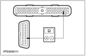
|
4 Measure the resistance between pin 50 of the C415 PCM connector, circuit 4-EC1 (grey-red), on the wiring side, and pin 6 of the C200 connector for the data link (DLC), electric circuit 4-EC1 (grey-red), from the side of the electrical wiring. |
|
• Is the resistance less than 2 ohms? |
|
|
→ Yes |
|
|
Go to Q7 |
|
|
→ No |
|
|
LOCATE and REPAIR open circuit 4-EC1 using the wiring diagrams (red-gray) between PCM and DLC. CHECK the system is working properly. |
|
|
Q7: 5-EC1 ELECTRICAL CIRCUIT CHECK (RED-BLUE) FOR A BREAK |
|
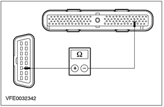
|
1 Measure the resistance between pin 49 of connector C415 PCM, circuit 5-EC1 (red-blue), on the wiring side, and pin 14 of the C200 DLC connector, electrical circuit 5-EC1 (red-blue), from the side of the electrical wiring. |
|
• Is the resistance less than 2 ohms? |
|
|
→ Yes |
|
|
Go to Q8 |
|
|
→ No |
|
|
LOCATE and REPAIR open circuit 5-EC1 using the wiring diagrams (red-blue) between PCM and DLC. CHECK the system is working properly. |
|
|
Q8: PCM ELECTRICAL VOLTAGE CHECK (THROUGH FUSE F20) |
|
|
1 Drive the ON position. |
|
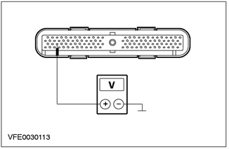
|
2 Measure the voltage on the circuit between C415 PCM connector pin 55, circuit 30-RE8 (red), from the wiring side, and "ground". |
|
• Does the battery voltage register? |
|
|
→ Yes |
|
|
Go to Q9 |
|
|
→ No |
|
|
LOCATE and REPAIR open circuit 30-LE8 using the wiring diagrams (red) between fuse F20 (BJB) and PCM. If necessary, INSTALL a new BJB. CHECK the system is working properly. |
|
|
Q9: PCM ELECTRICAL VOLTAGE CHECK (THROUGH THE FUSE F9) |
|

|
1 Measure the voltage in the circuit between pin 71, circuit 15-RE8 (yellow-green), and accordingly pin 97, electrical circuit 15-RE8A (yellow-green), C415 PCM connector, wiring side, and ground. |
|
• Does the battery voltage register? |
|
|
→ Yes |
|
|
Go to Q10 |
|
|
→ No |
|
|
Both measurements do not indicate battery voltage: using the wiring diagrams, LOCATE and REPAIR the open circuit between fuse F9 and splice S54. CHECK the system is working properly. |
|
|
One measurement does not indicate battery voltage: Using the wiring diagrams, LOCATE and REPAIR the open in circuit 15-RE8 or 15-RE8A between splice S54 and PCM. CHECK the system is working properly. |
|
|
Q10: PCM GROUND CIRCUIT CHECK (VIA G1) |
|
|
1 Enter the OFF position. |
|
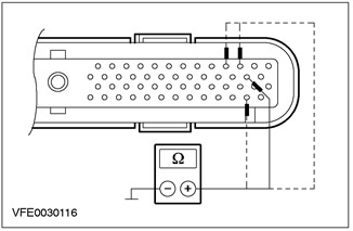
|
2 Measure the resistance between pin 103, circuit 91-RE8C (black and yellow), and, accordingly, pin 51, electrical circuit 91-RE8B (black and yellow), and accordingly pin 24, electrical circuit 91-RE8A (black and yellow), and, accordingly, pin 23, electrical circuit 91-RE8E (black and yellow), C415 PCM connector, wiring side, and ground. |
|
• Is the resistance less than 2 ohms for each measurement? |
|
|
→ Yes |
|
|
Go to Q11 |
|
|
→ No |
|
|
One measurement shows more than 2 ohms: Using the wiring diagrams, LOCATE and REPAIR the open in circuit 91-RE8C, 91-RE8B, or 91-RE8A between PCM and splice S53. CHECK the system is working properly. |
|
|
All measurements show greater than 2 ohms: using the wiring diagrams, LOCATE and REPAIR the open circuit between splice S53 and ground point G1. CHECK the system is working properly. |
|
|
Q11: PCM GROUND CIRCUIT CHECK (VIA G1) |
|
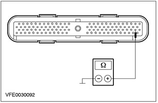
|
1 Measure the resistance between pin 77 of connector C415 PCM, circuit 91-RE8 (black and yellow), from the wiring side, and "ground". |
|
• Is the resistance less than 2 ohms? |
|
|
→ Yes |
|
|
Go to Q12 |
|
|
→ No |
|
|
Using the wiring diagrams, LOCATE and REPAIR the open in circuit 91-RE8 between the PCM and ground point G1. CHECK the system is working properly. |
|
|
Q12: PCM GROUND CIRCUIT CHECK (VIA G1) |
|
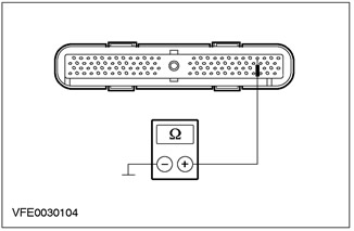
|
1 Measure the resistance between pin 23 of connector C415 PCM, circuit 91-RE8E (black and yellow), from the wiring side, and "ground". |
|
• Is the resistance less than 2 ohms? |
|
|
→ Yes |
|
|
Go to Q13 |
|
|
→ No |
|
|
Using the wiring diagrams, LOCATE and REPAIR the open in circuit 91-RE8E between the PCM and splice S53. CHECK the system is working properly. |
|
|
Q13: PCM GROUND CIRCUIT CHECK (VIA G24) |
|

|
1 Measure the resistance between pin 25 of connector C415 PCM, circuit 31-RE8 (black), from the wiring side, and "ground". |
|
• Is the resistance less than 2 ohms? |
|
|
→ Yes |
|
|
CHECK PCM, INSTALL a new one if necessary. CHECK the system is working properly. |
|
|
→ No |
|
|
Using the wiring diagrams, LOCATE and REPAIR the open in circuit 31-RE8 between the PCM and ground point G24. CHECK the system is working properly. |
|
PINPOINT TEST R: NO MODULE / COMMUNICATION WITH MODULES (BUS SCP)
|
STATES |
DETAILS/RESULTS/ACTIONS |
|
R1: SYSTEM CHECK USING WDS. |
|
|
1 Enter the OFF position. |
|
|
2 Connect the diagnostic tool. |
|
|
3 Check the system using WDS. |
|
|
• Are any DTCs logged? (DTC). |
|
|
→ Yes |
|
|
Take appropriate action on DTCs as directed by WDS. CLEAR fault memory and CHECK system for correct operation. |
|
|
→ No |
|
|
Go to R2 |
|
|
R2: PIN 2 ELECTRICAL CIRCUIT CHECK (BUS SCP) CONNECTOR OF THE DATA TRANSMISSION CHANNEL FOR A SHORT CIRCUIT TO THE ELECTRIC POWER CIRCUIT |
|
|
1 Drive the ON position. |
|

|
2 Measure the voltage between pin 2 of the C200 DLC plug, circuit 4-EG7 (grey-red), from the wiring side, and "ground". |
|
• Is any voltage being registered? |
|
|
→ Yes |
|
|
Go to R4 |
|
|
→ No |
|
|
Go to R3 |
|
|
R3: PIN CHECK 10 DLC (BUS SCP-) FOR A SHORT CIRCUIT IN THE ELECTRICAL POWER CIRCUIT |
|
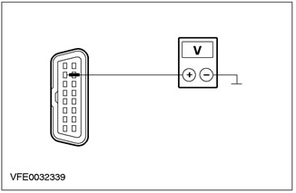
|
1 Measure the voltage between pin 10 of the C200 DLC plug, circuit 5-EG7 (red-blue), from the wiring side, and "ground". |
|
• Is any voltage being registered? |
|
|
→ Yes |
|
|
Go to R5 |
|
|
→ No |
|
|
Go to R6 |
|
|
R4: DETERMINING THE PRESENCE OF A SHORT CIRCUIT TO THE POWER SUPPLY CIRCUIT POSSIBLY CAUSED BY ANY MODULE |
|
|
1 Enter the OFF position. |
|
|
2 Detach One listed element and then the next according to the following checkpoints (points 3 and 4):. - C539 electronic automatic temperature control module (EATC) - C415 (EEC V with 104-pin connector) and respectively C416 (EEC V with 60-pin connector) and respectively C414 (EEC V with 121-pin connector) powertrain control module (PCM) - C840 of the ABS module and respectively the module of the electronic stability program on the course (ESP) - C809 instrument panel - C853 auxiliary instrument panel |
|
|
3 Drive the ON position. |
|
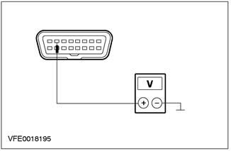
|
4 Measure the voltage between pin 2 of the C200 DLC plug, circuit 4-EG7 (grey-red), from the wiring side, and "ground". |
|
• Is any voltage being registered? |
|
|
→ Yes |
|
|
Not all relevant components are disconnected: Switch off the ignition. Detach next item (go to point 1). |
|
|
All relevant items are disconnected: LOCATE and REPAIR short to power in circuits connected to DLC pin 2 using the wiring diagrams. CHECK the system is working properly. |
|
|
→ No |
|
|
The last disconnected element caused a malfunction, CHECK the element, INSTALL a new one if necessary. CHECK the system is working properly. |
|
|
R5: DETERMINING THE PRESENCE OF A SHORT CIRCUIT IN THE ELECTRICAL POWER CIRCUIT POSSIBLY CAUSED BY ANY MODULE |
|
|
1 Enter the OFF position. |
|
|
2 Detach One listed element and then the next according to the following checkpoints (points 3 and 4):. - C539 electronic automatic temperature control module (EATC) - C415 (EEC V with 104-pin connector) and respectively C416 (EEC V with 60-pin connector) and respectively C414 (EEC V with 121 pin connector) powertrain control module - C840 of the ABS module and respectively the module of the electronic stability program on the course (ESP) - C809 instrument panel - C853 auxiliary instrument panel |
|
|
3 Drive the ON position. |
|

|
4 Measure the voltage between pin 10 of the C200 DLC plug, circuit 5-EG7 (red-blue), from the wiring side, and "ground". |
|
• Is any voltage being registered? |
|
|
→ Yes |
|
|
Not all relevant components are disconnected: Switch off the ignition. Detach next item (go to point 1). |
|
|
All relevant items are disconnected: LOCATE and REPAIR shorts to power in the circuits connected to DLC pin 10 using the wiring diagrams. CHECK the system is working properly. |
|
|
→ No |
|
|
The last disconnected element caused a malfunction, CHECK the element, INSTALL a new one if necessary. CHECK the system is working properly. |
|
|
R6: CHECK PIN 2 DLC (BUS SCP) FOR A SHORT TO « GROUND » |
|
|
1 Enter the OFF position. |
|

|
2 Measure the resistance between pin 2 of the C200 DLC connector, circuit 4-EG7 (grey-red), from the wiring side, and "ground". |
|
• Is the resistance greater than 10 kΩ? |
|
|
→ Yes |
|
|
Go to R7 |
|
|
→ No |
|
|
Go to R8 |
|
|
R7: CHECK PIN 10 DLC (BUS SCP) FOR A SHORT TO « GROUND » |
|
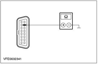
|
1 Measure the resistance between pin 10 of the C200 DLC connector, circuit 5-EG7 (red-blue), from the wiring side, and "ground". |
|
• Is the resistance greater than 10 kΩ? |
|
|
→ Yes |
|
|
Go to R10 |
|
|
→ No |
|
|
Go to R9 |
|
|
R8: DETERMINING THE PRESENCE OF A SHORT CIRCUIT TO THE ELECTRICAL POWER CIRCUIT POSSIBLY CAUSED BY ANY MODULE |
|
|
1 Detach One listed element and then the next according to the next check item (point 2):. - C539 electronic automatic temperature control module (EATC) - C415 (EEC V with 104-pin connector) and respectively C416 (EEC V with 60-pin connector) and respectively C414 (EEC V with 121 pin connector) powertrain control module (PCM) - C840 of the ABS module and respectively the module of the electronic stability program on the course (ESP) - C809 instrument panel - C853 auxiliary instrument panel |
|

|
2 Measure the resistance between pin 2 of the C200 DLC connector, circuit 4-EG7 (grey-red), from the wiring side, and "ground". |
|
• Is the resistance greater than 10 kΩ? |
|
|
→ Yes |
|
|
The last disconnected element caused a malfunction, CHECK the element, INSTALL a new one if necessary. CHECK the system is working properly. |
|
|
→ No |
|
|
Not all relevant items are detached. Detach next item (go to point 1). |
|
|
All relevant items are disconnected: LOCATE and REPAIR short to ground in circuits connected to DLC pin 2 using the wiring diagrams. CHECK the system is working properly. |
|
|
R9: DETERMINING THE PRESENCE OF A SHORT CIRCUIT TO THE POWER SUPPLY CIRCUIT POSSIBLY CAUSED BY ANY MODULE |
|
|
1 Detach One listed element and then the next according to the next check item (point 2):. - C539 electronic automatic temperature control module (EATC) - C415 (EEC V with 104-pin connector) and respectively C416 (EEC V with 60-pin connector) and respectively C414 (EEC V with 121 pin connector) powertrain control module (PCM) - C840 of the ABS module and respectively the module of the electronic stability program on the course (ESP) - C809 instrument panel - C853 auxiliary instrument panel |
|

|
2 Measure the resistance between pin 10 of the C200 DLC plug, circuit 5-EG7 (red-blue), from the wiring side, and "ground". |
|
• Is the resistance greater than 10 kΩ? |
|
|
→ Yes |
|
|
The last disconnected element caused a malfunction, CHECK the element, INSTALL a new one if necessary. CHECK the system is working properly. |
|
|
→ No |
|
|
Not all matching elements are detached: detach the next element (go to point 1). |
|
|
All relevant items are disconnected: LOCATE and REPAIR short to ground in circuits connected to DLC pin 10 using the wiring diagrams. CHECK the system is working properly. |
|
|
R10: 4-EG7 ELECTRICAL CIRCUIT CHECK (GRAY-RED) GAP BETWEEN PCM AND DLC |
|
|
1 Disconnect C415 PCM (EEC V with 104-pin connector) and respectively C416 (EEC V with 60-pin connector) powertrain control module (PCM). |
|
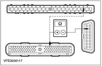
|
2 Measure the resistance between pin 16 of the C415 PCM connector (and respectively pin 19 C416), electrical circuit 4-EG9 (grey-orange), on the wiring side, and pin 2 of the C200 DLC plug connector, electrical circuit 4-EG7 (grey-red). |
|
• Is the resistance less than 2 ohms? |
|
|
→ Yes |
|
|
Go to R11 |
|
|
→ No |
|
|
LOCATE and REPAIR open circuit 4-EG9 using the wiring diagrams (grey-orange) and accordingly 4-EG7 (grey-red) between PCM and DLC using the wiring diagrams. CHECK the system is working properly. |
|
|
R11: 5-EG7 ELECTRICAL CIRCUIT CHECK (RED-BLUE) GAP BETWEEN PCM AND DLC |
|

|
1 Measure the resistance between pin 15 of the C415 PCM connector (and respectively pin 18 C416), electrical circuit 5-EG9 (black and blue), on the wiring side, and pin 10 of the C200 DLC connector, electrical circuit 5-EG7 (red-blue), from the side of the electrical wiring. |
|
• Is the resistance less than 2 ohms? |
|
|
→ Yes |
|
|
CHECK PCM, INSTALL a new one if necessary. CHECK the system is working properly. |
|
|
→ No |
|
|
LOCATE and REPAIR open circuit 5-EG9 using the wiring diagrams (black and blue) and accordingly 5-EG7 (red-blue) between PCM and DLC using the wiring diagrams. CHECK the system is working properly. |
|
PINPOINT TEST S: NO MODULE/NETWORK (CAN BUS) (ONLY ENDURA-DI AND DURATORQ TDCI, TWO-SECTION MODULE)
|
STATES |
DETAILS/RESULTS/ACTIONS |
|
S1: SYSTEM CHECK USING WDS. |
|
|
1 Enter the OFF position. |
|
|
2 Connect the diagnostic tool. |
|
|
3 Check the system using WDS. |
|
|
• Are any DTCs logged? (DTC). |
|
|
→ Yes |
|
|
Take appropriate action on DTCs as directed by WDS. CLEAR fault memory and CHECK system for correct operation. |
|
|
→ No |
|
|
DuraTorq TDCi: Go to S2 |
|
|
Endura-DI: Go to S12 |
|
|
S2: INJECTOR CONTROL MODULE VOLTAGE CHECK (IDM) |
|
|
1 Enter the OFF position. |
|
|
2 Disconnect C418 injector control module (IDM). |
|
|
3 Drive the ON position. |
|
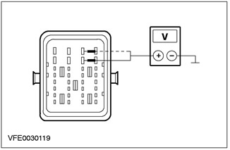
|
4 Measure the voltage between pin G2 of C418 IDM plug connector, circuit 15S-RS4A (green-yellow), and accordingly pin H2, electrical circuit 15S-RS4B (green-yellow), from the wiring side, and "ground". |
|
• Does the battery voltage register? |
|
|
→ Yes |
|
|
Go to S3 |
|
|
→ No |
|
|
LOCATE and REPAIR the open circuit between splice S90 and IDM using the wiring diagrams. CHECK the system is working properly. |
|
|
S3: VOLTAGE CHECK IN IDM |
|
|
1 Enter the OFF position. |
|
|
2 Disconnect C419 IDM. |
|
|
3 Drive the ON position. |
|
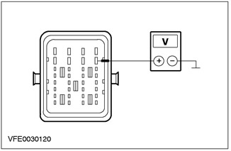
|
4 Measure the voltage between pin G1 of C419 IDM plug connector, circuit 15S-RS4C (green-yellow), from the wiring side, and "ground". |
|
• Does the battery voltage register? |
|
|
→ Yes |
|
|
Go to S4 |
|
|
→ No |
|
|
LOCATE and REPAIR the open in circuit 15S-RS4C between splice S90 and IDM using the wiring diagrams. CHECK the system is working properly. |
|
|
S4: IDM GROUND CHECK |
|
|
1 Enter the OFF position. |
|
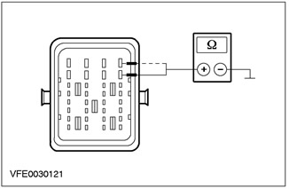
|
2 Measure the resistance between pin G1 of the C418 IDM connector, circuit 91-RS4A (black and yellow) and, accordingly, pin H1, electrical circuit 91-RS4B (black and yellow), from the wiring side, and "ground". |
|
• Is the resistance less than 2 ohms? |
|
|
→ Yes |
|
|
Go to S5 |
|
|
→ No |
|
|
LOCATE and REPAIR the open in the appropriate electrical circuit between the IDM and the G1 ground point using the wiring diagrams. CHECK the system is working properly. |
|
|
S5: IDM GROUND CHECK |
|
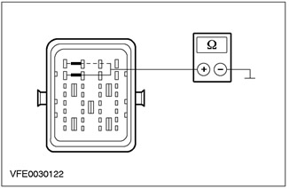
|
1 Measure the resistance between pin G4 of the C419 IDM connector, circuit 91-RS4D (black and yellow)? and, accordingly, pin H4, electrical circuit 91-RS4C (black and yellow), from the wiring side, and "ground". |
|
• Is the resistance less than 2 ohms? |
|
|
→ Yes |
|
|
Go to S6 |
|
|
→ No |
|
|
LOCATE and REPAIR the open circuit between the IDM and G1 ground using the wiring diagrams. CHECK the system is working properly. |
|
|
S6: 4-EC7 ELECTRICAL CIRCUIT CHECK (RED-GRAY) AND ACCORDINGLY 5-EC7 (RED-BLUE) FOR A SHORT CIRCUIT IN THE ELECTRICAL POWER CIRCUIT |
|
|
1 Drive the ON position. |
|

|
2 Measure the voltage between pin A4 of the C418 IDM connector, circuit 4-EC7 (grey-red), and respectively pin A3, electrical circuit 5-EC7 (red-blue), from the wiring side, and "ground". |
|
• Is the battery voltage recorded with every measurement? |
|
|
→ Yes |
|
|
Go to S7 |
|
|
→ No |
|
|
Go to S8 |
|
|
S7: POWER PACK CONTROL MODULE CHECK (PCM) FOR A SHORT CIRCUIT IN THE ELECTRICAL POWER CIRCUIT |
|
|
1 Enter the OFF position. |
|
|
2 Disconnect the C415 PCM. |
|
|
3 Drive the ON position. |
|

|
4 Measure the voltage between pin A4 of the C418 IDM connector, circuit 4-EC7 (grey-red), and respectively pin A3, electrical circuit 5-EC7 (red-blue), from the wiring side, and "ground". |
|
• Is the battery voltage recorded with every measurement? |
|
|
→ Yes |
|
|
Using the wiring diagrams, LOCATE and REPAIR the short to power on the appropriate circuit. CHECK the system is operating correctly. |
|
|
→ No |
|
|
CHECK PCM, INSTALL a new one if necessary. CHECK the system is working properly. |
|
|
S8: 4-EC7 ELECTRICAL CIRCUIT CHECK (RED-GRAY) AND ACCORDINGLY 5-EC7 (RED-BLUE) FOR A SHORT TO « GROUND » |
|
|
1 Enter the OFF position. |
|
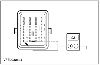
|
2 Measure the resistance between pin A4 of the C418 IDM connector, circuit 4-EC7 (grey-red) and, accordingly, pin A3, electrical circuit 5-EC7 (red-blue), from the wiring side, and "ground". |
|
• Is the resistance greater than 10 kΩ for both measurements? |
|
|
→ Yes |
|
|
Go to S10 |
|
|
→ No |
|
|
Go to S9 |
|
|
S9: POWER PACK CONTROL MODULE CHECK (PCM) FOR A SHORT TO « GROUND » |
|
|
1 Disconnect the C415 PCM. |
|

|
2 Measure the resistance between pin A4 of the C418 IDM connector, circuit 4-EC7 (grey-red), and respectively pin A3, electrical circuit 5-EC7 (red-blue), from the wiring side, and "ground". |
|
• Is the resistance greater than 10 kΩ for both measurements? |
|
|
→ Yes |
|
|
CHECK PCM, INSTALL a new one if necessary. CHECK the system is working properly. |
|
|
→ No |
|
|
Using the wiring diagrams, LOCATE and REPAIR the short to ground in the appropriate circuit. CHECK the system is working properly. |
|
|
S10: 4-EC7 ELECTRICAL CIRCUIT CHECK (RED-GRAY) FOR A BREAK |
|
|
1 Disconnect C415 powertrain control module (RSM). |
|
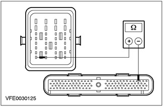
|
2 Measure the resistance between pin A4 of connector C418 IDM, circuit 4-EC7 (red-gray), on the wiring side, and pin 50 of the C415 PCM connector, circuit 4-EC7 (red-gray), from the side of the electrical wiring. |
|
• Is the resistance less than 2 ohms? |
|
|
→ Yes |
|
|
Go to S11 |
|
|
→ No |
|
|
LOCATE and REPAIR open circuit 4-EC7 (grey-red) between IDM and PCM using wiring diagrams. CHECK the system is working properly. |
|
|
S11: 5-EC7 ELECTRICAL CIRCUIT CHECK (RED-BLUE) FOR A BREAK |
|
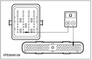
|
1 Measure the resistance between pin A3 of connector C418 IDM, circuit 5-EC7 (red-blue), wiring side, and pin 49 of C415 PCM connector, circuit 5-EC7 (red-blue), from the side of the electrical wiring. |
|
• Is the resistance less than 2 ohms? |
|
|
→ Yes |
|
|
CHECK IDM, if necessary INSTALL a new one. CHECK the system is working properly. |
|
|
→ No |
|
|
LOCATE and REPAIR open circuit 5-EC7 (red-blue) between IDM and PCM using wiring diagrams. CHECK the system is working properly. |
|
|
S12: DIESEL FUEL PUMP VOLTAGE CHECK |
|
|
1 Enter the OFF position. |
|
|
2 Disconnect the C728 diesel fuel pump. |
|
|
3 Drive the ON position. |
|
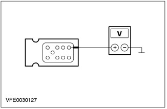
|
4 Measure the voltage on the circuit between pin 7 of the diesel fuel pump connector C728, circuit 15S-RS4 (yellow-green), from the wiring side, and "ground". |
|
• Does the battery voltage register? |
|
|
→ Yes |
|
|
Go to S13 |
|
|
→ No |
|
|
Using the wiring diagrams, LOCATE and REPAIR the open circuit between fuse F12 and diesel fuel pump. CHECK the system is working properly. |
|
|
S13: DIESEL FUEL PUMP GROUND CIRCUIT CHECK |
|
|
1 Enter the OFF position. |
|
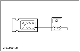
|
2 Measure the resistance between pin 6 of the diesel fuel pump connector C728, circuit 91-RS4 (black and yellow), from the wiring side, and "ground". |
|
• Is the resistance less than 2 ohms? |
|
|
→ Yes |
|
|
Go to S14 |
|
|
→ No |
|
|
Using the wiring diagrams, LOCATE and REPAIR the open in the electrical circuit between the diesel fuel pump and ground point G1. CHECK the system is working properly. |
|
|
S14: 4-EC7 ELECTRICAL CIRCUIT CHECK (RED-GRAY) AND ACCORDINGLY 5-EC7 (RED-BLUE) FOR A SHORT CIRCUIT IN THE ELECTRICAL POWER CIRCUIT |
|
|
1 Drive the ON position. |
|

|
2 Measure the voltage in the circuit between pin 2, circuit 4-EC7 (red-gray), and accordingly pin 1, electrical circuit 5-EC7 (red-blue), diesel fuel pump connector C728, wiring side, and ground. |
|
• Is the battery voltage recorded with every measurement? |
|
|
→ Yes |
|
|
Go to S15 |
|
|
→ No |
|
|
Go to S16 |
|
|
S15: POWER PACK CONTROL MODULE CHECK (PCM) FOR A SHORT CIRCUIT IN THE ELECTRICAL POWER CIRCUIT |
|
|
1 Enter the OFF position. |
|
|
2 Disconnect the C415 PCM. |
|
|
3 Drive the ON position. |
|

|
4 Measure the voltage in the circuit between pin 2, circuit 4-EC7 (red-gray), and accordingly pin 1, electrical circuit 5-EC7 (red-blue), diesel fuel pump connector C728, wiring side, and ground. |
|
• Is the battery voltage recorded with every measurement? |
|
|
→ Yes |
|
|
Using the wiring diagrams, LOCATE and REPAIR the short to power circuit in the appropriate circuit. CHECK the system is working properly. |
|
|
→ No |
|
|
CHECK PCM, INSTALL a new one if necessary. CHECK the system is working properly. |
|
|
S16: 4-EC7 ELECTRICAL CIRCUIT CHECK (RED-GRAY) AND ACCORDINGLY 5-EC7 (RED-BLUE) FOR A SHORT TO « GROUND » |
|
|
1 Enter the OFF position. |
|
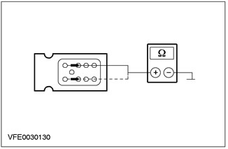
|
2 Measure the resistance between pin 2, circuit 4-EC7 (red-gray), and accordingly pin 1, electrical circuit 5-EC7 (red-blue), diesel fuel pump connector C728, wiring side, and ground. |
|
• Is the resistance greater than 10 kΩ for both measurements? |
|
|
→ Yes |
|
|
Go to S18 |
|
|
→ No |
|
|
Go to S17 |
|
|
S17: POWER PACK CONTROL MODULE CHECK (PCM) FOR A SHORT TO « GROUND » |
|
|
1 Disconnect the C415 PCM. |
|

|
2 Measure the resistance between pin 2, circuit 4-EC7 (red-gray), and accordingly pin 1, electrical circuit 5-EC7 (red-blue), diesel fuel pump connector C728, wiring side, and ground. |
|
• Is the resistance greater than 10 kΩ for both measurements? |
|
|
→ Yes |
|
|
CHECK PCM, INSTALL a new one if necessary. CHECK the system is working properly. |
|
|
→ No |
|
|
Using the wiring diagrams, LOCATE and REPAIR the short to ground in the appropriate circuit. CHECK the system is working properly. |
|
|
S18: 4-EC7 ELECTRICAL CIRCUIT CHECK (RED-GRAY) FOR A BREAK |
|
|
1 Disconnect C415 powertrain control module (RSM). |
|
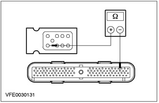
|
2 Measure the resistance between pin 2 of connector C728, diesel fuel pump, circuit 4-EC7 (red-gray), on the wiring side, and pin 50 of the C415 PCM connector, circuit 4-EC7 (red-gray), from the side of the electrical wiring. |
|
• Is the resistance less than 2 ohms? |
|
|
→ Yes |
|
|
Go to S19 |
|
|
→ No |
|
|
LOCATE and REPAIR open circuit 4-EC7 using the wiring diagrams (red-gray) between the diesel fuel pump and the PCM. CHECK the system is working properly. |
|
|
S19: 5-EC7 ELECTRICAL CIRCUIT CHECK (RED-BLUE) FOR A BREAK |
|
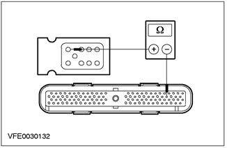
|
1 Measure the resistance between pin 1 of the diesel fuel pump connector C728, circuit 5-EC7 (red-blue), wiring side, and pin 49 of C415 PCM connector, circuit 5-EC7 (red-blue), from the side of the electrical wiring. |
|
• Is the resistance less than 2 ohms? |
|
|
→ Yes |
|
|
CHECK the diesel fuel pump, INSTALL a new one if necessary. CHECK the system is working properly. |
|
|
→ No |
|
|
LOCATE and REPAIR open circuit 5-EC7 using the wiring diagrams (red-blue) between the diesel fuel pump and the PCM. CHECK the system is working properly. |
|
Checking the elements
Power Maintenance Relay
1. Check the normally open contact in a non-switching state.
- Measure the resistance between pins 3 and 5 of the relay, element side.
- Is the registered resistance greater than 10 kΩ? If yes, go to step 2. If not, replace the relay.
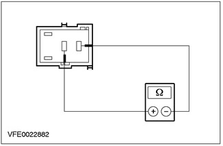
2. Check the normally open contact in the switching state.
- Using a fused test lead (1 A), connect relay pin 1, cell side, to battery positive.
- Using a test lead, connect relay pin 2, cell side, to the negative battery terminal.
- Measure the resistance between pins 3 and 5 of the relay, element side.
- Is resistance less than 2 ohms registered? If so, the relay is OK. If not, REPLACE the relay.
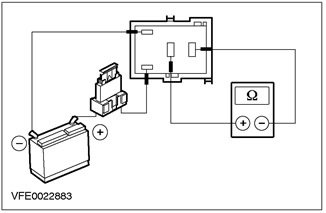
Visitor comments