|
STATES |
DETAILS/RESULTS/ACTIONS |
|
A1: CHECK ELECTRICAL CIRCUIT 8-EE7 FOR OPEN |
|
|
1Enter the OFF position. |
|
|
2Disconnect C424 airbag module. |
|
|
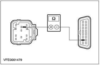
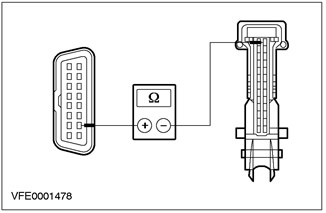
3Measure the resistance between air bag module connector C424 pin 7 and DLC connector C200 pin 7, circuit 8-EE7 (WH/RD) and 8-EE10 (WH/BLK). |
|
• Is the connector OK and the resistance is less than 2 ohms? |
|
|
→ Yes |
|
|
Go to A2 |
|
|
→ No |
|
|
REPAIR connector or circuit 8-EE7. CHECK system operation for proper operation |
|
|
A2: CHECK CIRCUIT 8-EE7 FOR SHORT TO GROUND" |
|
|
1Enter the OFF position. |
|
|
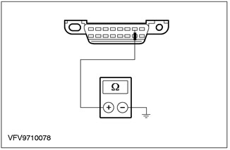
2Measure the resistance between pin 7 of the C200 DLC connector, circuit 8-EE7 (WH/RD) and ground. |
|
• Is the resistance more than 1000 ohms? |
|
|
→ Yes |
|
|
Go to A3 |
|
|
→ No |
|
|
REPAIR connector or circuit 8-EE7. CHECK system operation for proper operation |
|
|
A3: CHECK CIRCUIT 8-EE7 FOR SHORT TO BATTERY VOLTAGE |
|
|
1Enter the ON position. |
|

|
2Measure the voltage between pin 7 of the C200 DLC connector, circuit 8-EE7 (WH/RD), and ground. |
|
• Is the voltage more than 1V? |
|
|
→ Yes |
|
|
REPAIR connector or circuit 8-EE7. CHECK system operation for proper operation |
|
|
→ No |
|
|
Go to A4 |
|
|
A4: CHECK DLC POWER SUPPLY |
|
|
1Download the FDS 2000 diagnostics for the central timer module and follow the on-screen instructions. |
|
|
• Are diagnostics performed? |
|
|
→ Yes |
|
|
REPLACE the airbag module CHECK the system for proper operation |
|
|
→ No |
|
|
REPAIR the power supply following the FDS 2000 instructions. CHECK the system for proper operation |
|
PINPOINT TEST B: ELECTRONIC STABILITY PROGRAM (ESP) MODULE DOES NOT RESPOND TO FDS 2000 SYSTEM REQUESTS
|
STATES |
DETAILS/RESULTS/ACTIONS |
|
B1: CHECK ELECTRICAL CIRCUIT 8-EE6 OR 8-EE6A FOR OPEN |
|
|
1Enter the OFF position. |
|
|
2Disconnect the Electronic Stability Program (ESP) Module C830. |
|
|
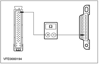
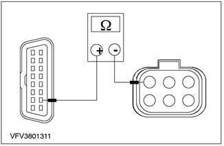
3Check connectors C830, C556 and C555 for damage and proper connection and measure the resistance between pin 17 of the Electronic Stability Program (ESP) module connector C830 and pin 7 of the C200 DLC, circuit 8-EE6A (WH), 8-EE6 (WH), 8-EE2 (WH/RED) and 8-EE10 (WH/BLK). |
|
• Are the connectors OK and the resistance is less than 2 ohms? |
|
|
→ Yes |
|
|
REPLACE the Electronic Stability Program (ESP) module. CHECK the system for proper operation |
|
|
→ No |
|
|
REPAIR connector or circuit 8-EE6 or 8-EE6A. CHECK system operation for proper operation |
|
PINPOINT TEST C: STEERING WHEEL POSITION SENSOR DOES NOT RESPOND TO FDS 2000 SYSTEM REQUESTS
|
STATES |
DETAILS/RESULTS/ACTIONS |
|
C1: CHECK ELECTRICAL CIRCUITS 4-EG15 AND 5-EG15 FOR OPENINGS |
|
|
1Enter the OFF position. |
|
|
2Disconnect the C818 Steering Wheel Position Sensor. |
|
|
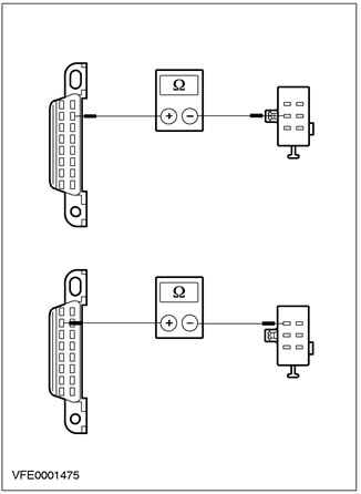
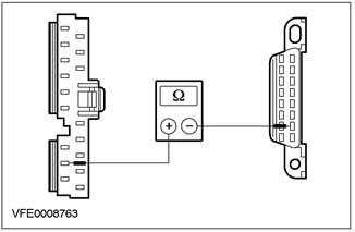
3Check connector C818 for damage and proper connection and measure the resistance between pin 2 of steering wheel position sensor connector C818 and pin 2 of C200 DLC, circuit 4-EG15 (Gray/Orange) and 4-EG7 (Gray/RED), and between pin 3 of C818 and pin 10 of C200, circuit 5-EG7 (Blue/RED) and 5-EG15 (Blue/Black). |
|
• Is the connector OK and the resistance is less than 2 ohms in both cases? |
|
|
→ Yes |
|
|
REPLACE the steering wheel position sensor. CHECK the system for proper operation |
|
|
→ No |
|
|
REPAIR connector C818 or circuit 4-EG15 between solder point S16 and connector C818, and circuit 5-EG15 between solder point S17 and connector C818. CHECK that the system operates correctly |
|
PINPOINT TEST D: ROUTE COMPUTER MODULE DOES NOT RESPOND TO FDS 2000 SYSTEM REQUESTS
|
STATES |
DETAILS/RESULTS/ACTIONS |
|
D1: CHECK ELECTRICAL CIRCUIT 8-EE12 FOR OPEN |
|
|
1Enter the OFF position. |
|
|
2Disconnect Trip Computer Module C467. |
|
|
3Check connector C467 for damage and proper connection and measure the resistance between pin 26 of the trip computer module connector C467 and pin 7 of the C200 DLC, circuit 8-EE12 (white) and 8-EE10 (white/black). |
|
• Is the connector OK and the resistance is less than 2 ohms? |
|
|
→ Yes |
|
|
REPLACE the trip computer module. CHECK the system for proper operation |
|
|
→ No |
|
|
REPAIR connector or circuit 8-EE12. CHECK system operation for proper operation |
|
PINPOINT TEST E: AUXILIARY HEATER DOES NOT RESPOND TO FDS 2000 OR NGS REQUESTS
|
STATES |
DETAILS/RESULTS/ACTIONS |
|
E1: CHECK ELECTRICAL CIRCUIT 8-EE11 FOR OPEN |
|
|
1Enter the OFF position. |
|
|
2Disconnect C878 auxiliary heater. |
|
|
3Check connectors C878 and C70 for damage and proper connection and measure the resistance between pin 3 of the auxiliary heater connector C878 and pin 7 of the C200 DLC, circuit 8-EE11 (white/purple) and 8-EE10 (white/black). |
|
• Are the plug connectors OK and the resistance is less than 2 ohms? |
|
|
→ Yes |
|
|
REPLACE the auxiliary heater. CHECK the system for proper operation |
|
|
→ No |
|
|
REPAIR connector or circuit 8-EE11 between C878 and solder point S140. CHECK system operation for proper operation |
|
PINPOINT TEST F: RADIO/ROAD COMMUNICATION SYSTEM MODULE DOES NOT RESPOND TO FDS 2000 OR NGS SYSTEM REQUESTS
|
STATES |
DETAILS/RESULTS/ACTIONS |
|
F1: CHECK ELECTRICAL CIRCUIT 8-MD15 FOR OPEN CIRCUIT |
|
|
1Enter the OFF position. |
|
|
2Disconnect the C447 Radio/Road Communication System Module. |
|
|
3Check connectors C447 and C445 for damage and proper connection and measure the resistance between pin 16 of the radio/road communication module connector C447 and pin 7 of the C200 DLC, circuit 8-MD15 (white/green) and 8-EE10 (white/black). |
|
• Are the plug connectors OK and the resistance is less than 2 ohms? |
|
|
→ Yes |
|
|
REPLACE the radio/road communication module. CHECK the system for proper operation |
|
|
→ No |
|
|
REPAIR connector or circuit 8-MD15. CHECK system operation for proper operation |
|
Content was created using data from this website [Fordbook.ru]