In general, removal and installation on all models under consideration are carried out in the same way. Some features of repair of certain models are given below.
Remove the steering gear as follows:
- disconnect the ground wire while observing the necessary safety precautions;
- set the steered wheels to the straight-ahead position;
- disconnect the nut and bolt of the steering knuckle shaft coupling from the gear in the engine compartment; to do this, unscrew the bolt and move the pressure plate to the side;
- carefully release the seal on the body (without damaging its working edges), to do this, release the fastening clamps on the back side, the clamp on the upper side, grab the seal from below and fold it upwards;
- find the clamping bolt of the steering friction clutch on the gear and unscrew the bolt with a suitable key, remove the clutch from the rear of the car from the gear;
- loosen the wheel nuts, lift the front of the car and place it on reliable supports or place the car on an inspection ditch or overpass;
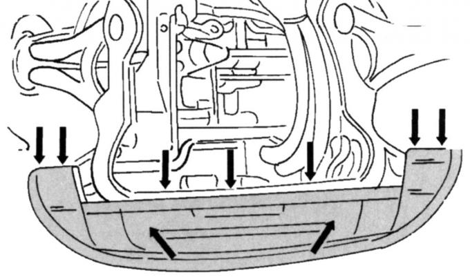
Fig. 232. Fastening the front wall to the rear side of the radiator
- remove the crankcase guard (if installed) and the front wall under the radiator (its mounting locations are shown in Fig. 232);
- disconnect the radiator hose of the cooling system and place the hose in a container to collect the leaking coolant;
- on a vehicle with a 2.5-liter engine, remove the catalytic converter as described in the relevant section;
- turn the wheels away;
- remove both trims on the right and left wheel arches (see Fig. 232);
- unscrew the shock absorber supports and move them to the side;
- remove the front wall of the left wing;
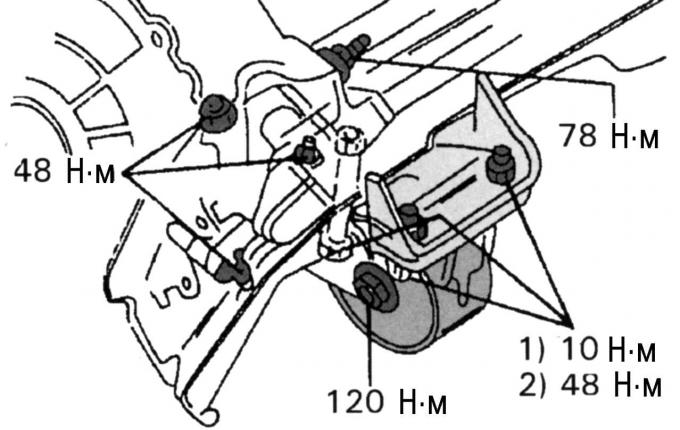
Fig. 233. Fastening the rear anti-rotation stop on a manual transmission
- remove the middle bolt of the rear anti-rotation stop (Fig. 233 and 234 show where this bolt is located in manual and automatic transmissions), for an automatic transmission, additionally unscrew bolt 1 (Fig. 235) in the middle and both nuts 2, and then the suspension bracket and the rear rubber stop;
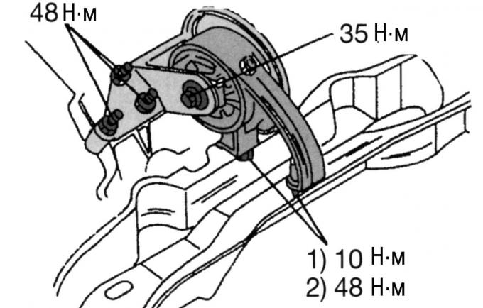
Fig. 234. Fastening the rear anti-rotation stop on an automatic transmission
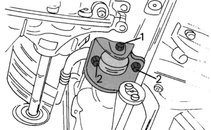
Fig. 235. Suspension bearing (cars with automatic transmission)
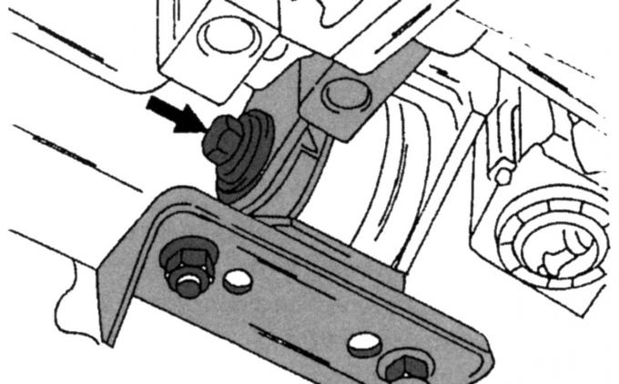
Fig. 170. Location of the front stop mounting screw
- remove the rear anti-rotation stop (see Fig. 170);
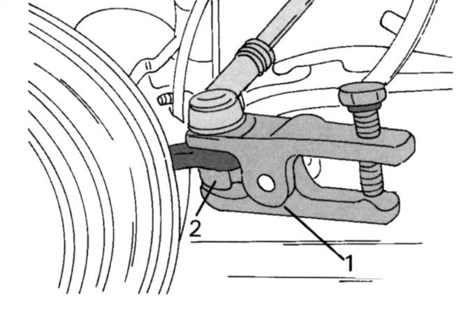
Fig. 236. Tie rod end remover
- unscrew the nut of the tie rod end on the trailing arm and separate the end with a special puller (Fig. 236);
- disconnect the anti-roll bar link on the top side of the shock absorber strut (one nut on each side);
- before unscrewing the mounting bolts, mark the position of the subframe and lower its extension onto the jack so that the coolant pipes are clearly visible;
- disconnect the union nuts of the pipes and remove their double clamps, plug the ends of the pipes and the resulting holes in the steering mechanism to protect them from contamination; collect the leaking liquid;
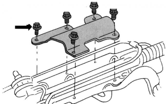
Fig. 237. Steering wheel guard (only on vehicles with 2.5-liter engine)
- on vehicles with a 2.5-liter engine, unscrew the protective cover of the steering control (located in the place shown in Fig. 237 and secured with bolts);
- unscrew both bolts securing the steering from the front cross member of the frame, remove the steering gear through the wheel well on the pinion side (while doing this, make sure that the check valve does not fall out of its channel);
- if necessary, unscrew the end of the transverse tie rod after loosening the lock nuts, be sure to record the number of turns required to unscrew each end, and tighten the new ends to the corresponding number of turns.
Install the steering control in the reverse order of removal, taking into account the following:
- insert the steering gear through the wheel arch and set it in the correct position, tighten both mounting bolts to a torque of 137 N·m, pay attention to the significant tightening torque;
- insert new sealing rings into the pipe connections (since the service station uses conical bushings for this operation, act especially carefully at this stage), connect the pipe and tighten the union nuts with a torque of 31 N·m, secure the double clamp with both bolts;
- in cars with a 2.5-liter engine, install the protective cover and tighten the bolts shown in Fig. 237 to a torque of 50 N·m, tighten the union nuts of the pipes to a torque of 31 N·m;
- connect the ball joints of the transverse steering rods, tighten the nuts to a torque of 37 N·m;
- in cars with a 2.5-liter engine, install the catalytic converter, tighten the flange connection at the front and rear to 40 N·m;
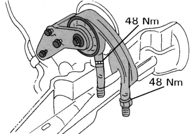
Fig. 238. Rear anti-rotation stop on automatic transmission
- if there is an automatic transmission, install the suspension bearing shown in Fig. 238 and tighten it to the specified tightening torques;
- install the subframe as described in the subsection "Installing the engine" and tighten the four mounting bolts (install it in the position marked before removal);
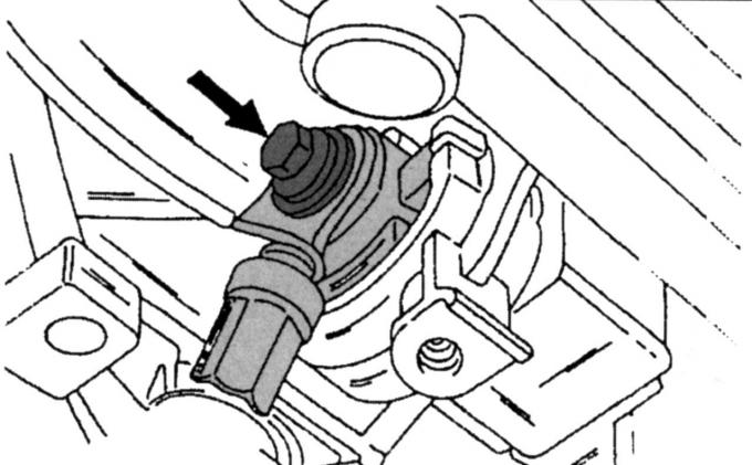
Fig. 239. Fastening the rear anti-rotation stop to the gearbox
- if there is an automatic transmission, install the rear stop against rotation (Fig. 239), tighten the bolt to a torque of 120 N·m;
- install the suspension bearing shown in Fig. 235, tighten bolt 1 to a torque of 25 N·m, nuts 2 to a torque of 48 N·m;
- if there is a manual transmission, tighten the middle bolt of the rear stop to a torque of 120 Nm;
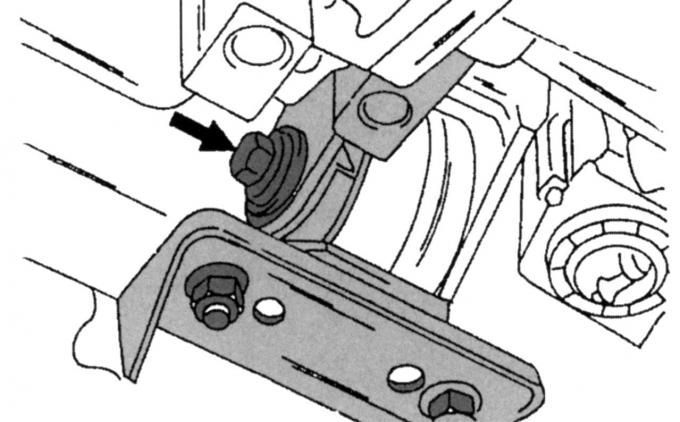
Fig. 240. Fastening to the support of the front stop against rotation
- on all vehicles, install the front torque support and tighten the bolts and nuts to 120 Nm (Fig. 240); if the bolts shown below have been removed, tighten them to 48 Nm;
- secure the anti-roll bar connecting rod (50 Nm);
- lower the car to the ground and tighten the wheel nuts to 85 Nm;
- install the steering gear coupling on the pinion, insert the bolts and tighten the new bolt to 19 Nm;
- carefully press the seal of the car body base, it should be located exactly in the groove of the steering gear coupling;
- install the steering column shaft pressure plate from the inside of the vehicle and tighten the new bolt to 24 Nm;
- connect the ground wire to the battery;
- fill the steering drive with working fluid and bleed it as described in the relevant section;
- check the wheel alignment, adjust if necessary.
The original article is available on the website FORDBOOK.RU