The following steps apply to vehicles equipped with dual-link control arms (side arms) manufactured before December 1997. For vehicles manufactured after that time, skip the instructions for attaching the side arm to the wheel bearing support.
Remove the transverse arm and coil springs as follows:
- Loosen the wheel nuts, raise the front of the car and remove the front wheels;
- compress the coil spring with suitable clamping hooks so that it is free between its seats;
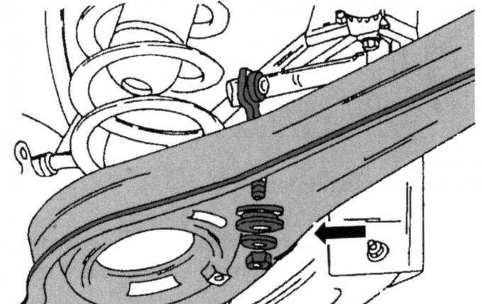
Fig. 219. Fastening the anti-roll bar link to the rear side of the wishbone
- place a jack under the frame cross member (to the side), unscrew the nut of the anti-roll bar link shown by the arrow in Fig. 219, remove the link from above;
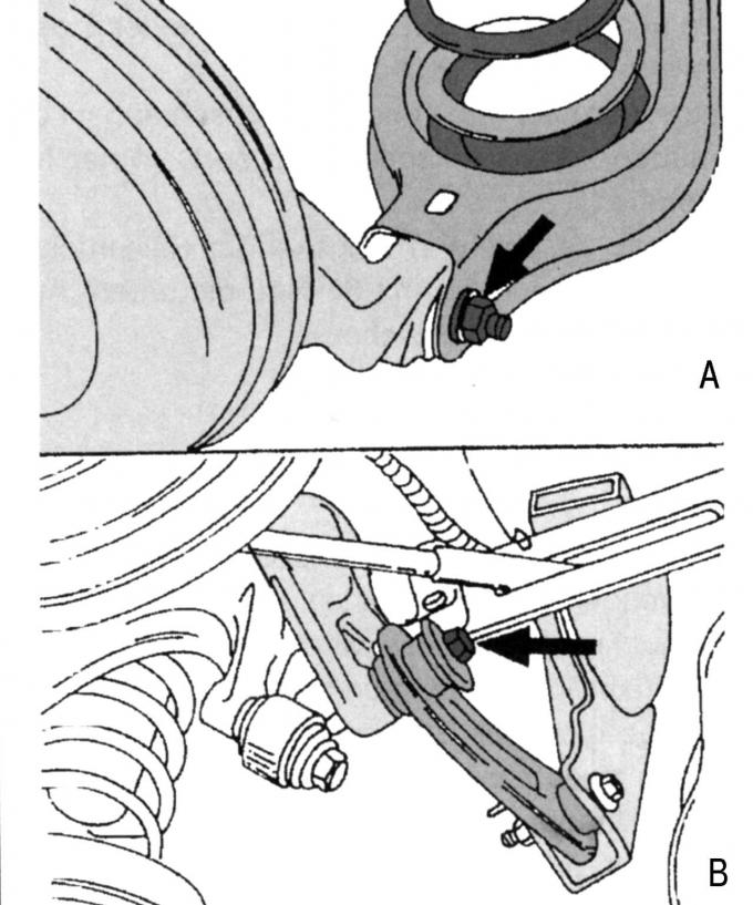
Fig. 220. Fastening the transverse arm (A) and lateral arm (B) to the hub
- release the cross member and lateral transverse arms from the mounting on the wheel hub support. Fig. 220 shows the mounting of the suspension arms.
- press down the transverse lever and remove the coil spring;
- unscrew the transverse arm from the inside of the frame cross member and remove it (pay attention to the eccentric head of the bolt and the eccentric washer located on the other side), before unscrewing, mark the position of the bolt head and washer.
Before assembly, all rubber suspension support elements must be installed only when the vehicle with wheels is on the ground.
Install the transverse arm in the following order:
- install the wishbone on the frame crossmember, install the eccentric washer and bolt head according to the marks made earlier, tighten the nut to a torque of 85 N·m;
- place the compressed coil spring on the transverse arm and lift the longitudinal arm to a height at which it can be attached to the hub (Fig. 220, A);
- connect the side arms shown in Fig. 220, tighten the nut to a torque of 120 Nm;
- connect the anti-roll bar link according to Fig. 219 and tighten the nut to a torque of 35 Nm.
- unscrew the tie and lower the car to the ground, then install the rubber support elements (to do this, the car must be installed with the rear part on the overpass), check the installation of the rear wheels;
- tighten the wheel nuts to a torque of 85 Nm.