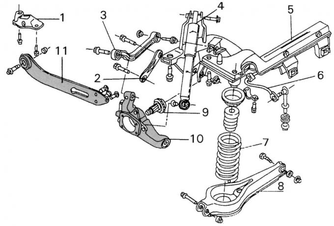
Fig. 215. Rear suspension (vehicles with a station wagon body manufactured before December 1997): 1 — jet thrust bearing block; 2 - rear side lever; 3 - Upper suspension arm; 4 — shock absorber; 5 — crossbar; 6 — anti-roll bar; 7 - coil spring; 8 - rear wishbone; 9 — butt element; 10 — wheel hub support; 11 - jet thrust
The removal and installation of the upper arm 3 (see Fig. 215) of the suspension is carried out in the same way as the removal and installation of the side arms described in Section 13.2.3. The tightening torques at the top and bottom are not the same. The upper fastening bolt 1, shown in Fig. 221, is tightened to a torque of 85 N·m, the lower bolt 2 - to a torque of 120 N·m.
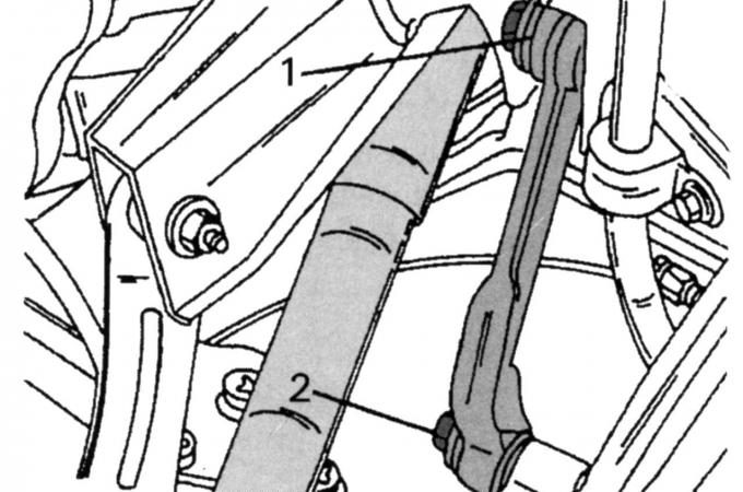
Fig. 221. Fastening the upper suspension arm: 1 - upper bolt, 85 N·m; 2 - lower bolt, 120 Nm
Note: Rubber suspension elements are tightened only under load.