


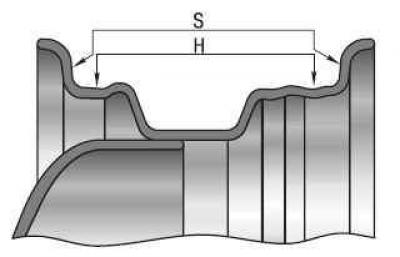
Fig. 12.2. Surfaces for measuring disk runout: H – radial runout; S – lateral runout
Fix the disk without the tire on the axis of the balancing device. Install the measuring tip of the dial indicator first on the radial and then on the lateral inner surface of the disk, on which the tire bead rests (Fig. 12.2).
Slowly rotate the balancing device disk by hand, while reading the indicator. Do not take into account the deviation of the indicator arrow from local protrusions or depressions on the disk.
If the maximum runout exceeds the permissible values, replace the disc.
NOTE: Maximum runout of steel disc: H = 0.8 mm, S = 1.0 mm.
NOTE: Maximum runout of alloy wheel: H = S = 1.5 mm.
(A copy of the article is available on the website FORDBOOK.RU)