Contents: Examination ↳ Adjustment ↳
Valve clearances only need to be checked/adjusted on a diesel engine. Petrol engines are equipped with hydraulic valve clearance compensators, which maintain the clearance constant. The following special tools are required to check/adjust valve clearances: a set of templates with a thickness change step of 0.05 mm, a device for holding valves in the lower position HAZET 3474 and special pliers for valves HAZET 3499. Wear parts include the cylinder head cover gasket and other parts.
To compensate for the various expansions of the valve train under the influence of heat, there must be a certain distance between the camshaft lobes and the corresponding bucket tappets. This distance for the valves changes over time due to the tighter grinding of the valves and wear of the valve train.
If the distance is too small, the valve timing changes, the result is poor compression, reduced engine power, and rough running. In extreme cases, the valves may become deformed, the valves themselves or the valve seats may burn.
If the distance is too large, strong mechanical noises occur, the valve timing changes, the valves in the engine open for a very short period of time, poor cylinder filling, reduced engine power, and uneven engine operation.
Valve clearances should be checked every 40,000 km as part of maintenance, and this should also be done after repairs if noise occurs in the valve timing mechanism: adjust the valve clearances if necessary.
Valve clearances are checked and adjusted on a cold engine (ambient temperature).
Examination
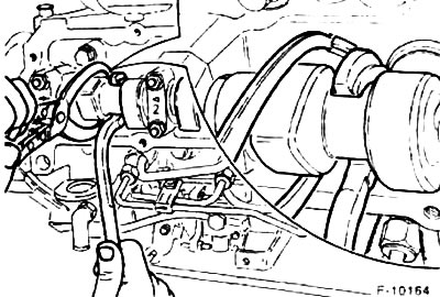
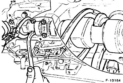
Remove the engine ventilation hoses from the cylinder head, first loosen the fastening clamps.
Remove the cylinder head cover by unscrewing three bolts.
Unscrew the oil deflector, it is secured under the cylinder head cover with four nuts.
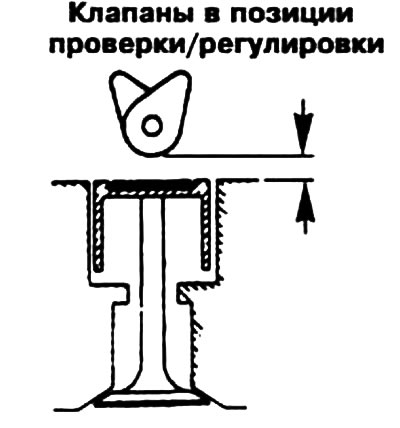
Turn the crankshaft until the pair of cams of the adjustable cylinder point upwards equally. There are three ways to turn the crankshaft:
- 1) Shift the transmission into neutral, apply the parking brake and place a ratchet wrench on the center bolt of the belt pulley;
- 2) engage fifth gear, release the parking brake and move the car a little;
- 3) Raise the car from the front right so that the wheel can rotate freely. Engage fifth gear and rotate the right front wheel by hand.
Slide a flat gauge between the cam and tappet and measure the valve clearance. Specified values for valve clearances (cold engine):
- Inlet valves: 0.35±0.05 mm;
- Exhaust valves: 0.50±0.05 mm;
Attention! Valve arrangement on the toothed belt side for all cylinders: 1st - inlet, 2nd - outlet valves.
A flat template of the appropriate thickness should pass between the cam and the plate tappet without any problems. Record the measurement result obtained.
Turn the crankshaft another 1/2 turn and check the valve clearance in the next cylinder, i.e. in the cylinder in which the ignition occurs. The ignition sequence is: 1-3-4-2.
Adjustment
To adjust the valve clearances, replace the existing adjusting washer with a new, thicker washer.
Attention! As the engine service life increases, valve clearances usually decrease due to lapping and running-in of the valves, i.e. this means that the existing washer must be replaced with a thinner one.
Example:
- Control tolerances: 0.030-0.40 mm (0.35±0.05 mm)
- Measured value: 0.25 mm
- Gap: 0.05mm is too small
If the measurement results are within the tolerance range, then the adjusting washer does not need to be changed. If the measurement result is outside the range, then when adjusting, you should strive to get the minimum value, here 0.35 mm.
Available adjusting washer: 3.85 mm.
Required shim: 3.75mm (to get the average value).
Adjust the valve clearances. For these purposes, Ford workshops use special tools 21-106 and 21-107 or HAZET-3474 and 3499. Without the mentioned tool, valve adjustment is impossible.
Caution! When adjusting valve clearances, the piston must not be at TDC, otherwise the valves and/or pistons may be damaged. Turn the crankshaft 1/4 turn.
Before setting the locking device in the lower position, turn the plate pushers so that when pressed down, the pliers can engage in the recesses.
Press the plate pusher together with the locking device in the lower position down and remove the adjusting washer. Finally, place the new washer so that the inscription faces down.
Remove the locking device in the lower position and turn the camshaft.
Adjust the valves of the other cylinders in exactly the same way.
Install the oil deflector into the cylinder head and tighten the four mounting nuts to a torque of 20 Nm.
Screw the cylinder head cover with a new seal. Lightly tighten the three bolts to 5 Nm, otherwise you will crush the seal.
Connect the engine ventilation hoses to the cylinder head cover and secure them with clamps.
The original source of the publication is on the website FordBook.ru