Contents: High Pressure Fuel Pump Review ↳ Cold start thrust adjustment ↳ Checking the idle speed, checking… ↳ Idle speed control, fast idle speed… ↳ Adjusting the engine speed reduction… ↳
High Pressure Fuel Pump Review
Since diesel engines do not have an ignition system, a special tachometer is required. This tachometer is expensive, so its purchase is not always justified. In addition to the tachometer, a 3 mm diameter pin (drill) and a set of flat templates are required. In case of adjustment, it is necessary to act as follows:
Cold start thrust adjustment
Function: The thermoelement is located in the coolant circuit on the thermostat housing and when the engine is cold, it activates the lever on the high-pressure fuel pump, and it activates it via the Bowden rod (cold start rod). Idling at higher speeds ensures quieter engine operation.
Warm up the engine, the coolant temperature should be 80°C. The coolant temperature indicator should be in the middle of the scale.
Finally, adjust the Bowden rod "9" of the heating element, see Fig. The fastening element should be at a distance of 1-2 mm from the lever of the high-pressure fuel pump, otherwise unscrew the fastening bolt on the fastening element and move the latter accordingly.
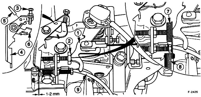
1 - Fuel lever; 2 - Fuel lever stop screw; 3 - Idle speed adjusting screw; 4 - Cold start lever; 5 - 3 mm pin; 6 - Idle speed lever; 7 - Adjusting tool; 8 - Template; 9 - Cold start thrust
Checking the idle speed, checking the fast idle
Check the idle speed and record it. The specified speed is 820-850 rpm.
The Ford 23016 idle speed adjustment template "7" together with a 1 mm thick template is pushed between the fuel pump lever "1" and the stop screw "2". If you do not have a Ford template, then a template or a 4 mm diameter drill can be clamped between the fuel pump lever and the idle speed adjustment screw.
Rotate the idle lever "6" clockwise and insert a 3 mm diameter pin into the hole. As a result, the idle lever is locked and the engine runs idle at high speed.
Check the accelerated speed and write down: specified speed: 800-1000 rpm.
If the idle speed and fast idle speed are normal, check the idle speed reduction period and adjust it if necessary.
Idle speed control, fast idle speed control
The engine should be hot and idling.
Place the Ford 23-016 template and a 1 mm thick template between the fuel pump lever "1" and the stop screw "2". The special tool "7" is installed on the stop of the adjusting screw, as a result, it is easier to turn it by hand. However, the tool can be omitted. If there is no Ford template, then clamp a flat template or a 4 mm thick drill between the fuel pump lever and the idle adjusting screw.
Turn the idle lever "6" clockwise and insert a 3 mm pin into the hole. The idle lever is locked as a result, the engine idles at higher speeds.
Loosen the lock nut and use the stop screw of the fuel pump lever "2" to adjust the idle speed to 900±100 rpm.
Remove the template, pin and Ford template. This will make the fuel pump lever contact the adjusting screw.
Loosen the lock nut and turn screw "3" until the speed reaches 820-850 rpm.
Finally, check the engine lag time and adjust it if necessary.
Adjusting the engine speed reduction period
The engine speed reduction period is the time it takes for the engine to go back from full throttle (maximum engine speed) to idle speed. If the engine speed decreases too quickly, the engine stalls. If the engine speed decreases too slowly, it causes driving problems and increases fuel consumption.
Apply full throttle (5150 rpm), release the accelerator pedal and time the time until the engine returns to idle speed. Specified time: maximum 5 sec.
Warning! Never give gas for more than three seconds. Do not give gas unnecessarily.
If you cannot get the specified value, then do the following:
The speed decreases too slowly: turn stop screw "2" counterclockwise by 1/4 turn, looking from the end of the pump.
The speed decreases too quickly: turn stop screw "2" clockwise by 1/4 turn.
Attention! Screw "2" must not be turned more than 1/4 turn.
Finally, check the idling speed again, the higher idling speed, adjust them if necessary.
Secure the adjusting screw with a lock nut.
The original article is posted at FordBook