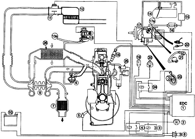
Schematic representation of the diesel fuel injection system: 1 - Control device (EDC); installation point: in the engine compartment, on the right wing; 2 - Air conditioning switch; 3 - Air conditioning compressor clutch; 4 - Air conditioner relay; 5 - Crankshaft speed sensor; 6 - Exhaust Gas Recirculation (EGR) Valve; 7 - Exhaust gas catalytic converter; 8 - Ignition switch; 9 - Turbocharger; 10 - Battery; 11 - Air flow meter; 12 - Air filter; 13 - Vacuum converter (CVT valve); 13a - Vacuum pump; 14 - Fuel tank; 15 - Fuel tank heating element; 16 - Fuel filter; 17 - High pressure fuel pump; 17a - Magnetic shut-off valve; 18 - Jet; 19 - Diagnostic plug; 20 - Plug for autotest; 21 - Fuel lever position sensor; 22 - Partial load magnetic valve; 23 - Cold mode magnetic switch; 24 - Cold mode relay; 25 - Coolant temperature sensor; 26 - Supply air cooling device
(The article was taken in its entirety from the specified website: FordBook.ru)