


You will need: a 14 mm wrench, special pullers for removing the compressor pulley and bearing retaining ring, a press or a device for pressing out bearings.
1. Remove the refrigerant from the air conditioning system (see Removing refrigerant from the air conditioning system) and disconnect the wire from the negative terminal of the battery.
2. Remove the compressor (see Removing and installing the compressor).
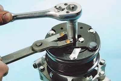
3. While holding the pressure plate from turning, unscrew the fastening nut…
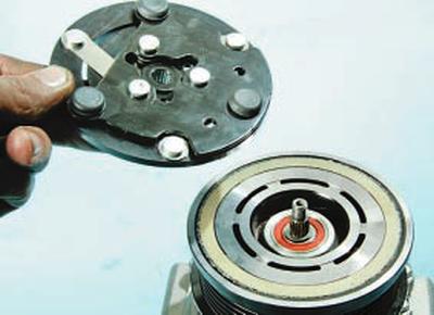
4….and remove the plate from the compressor shaft.
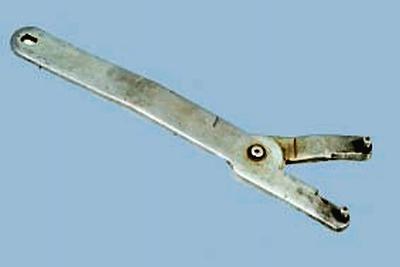
HELPFUL TIP: Use a special device to hold the compressor pressure plate from turning.
NOTE: If the pressure plate has rusted to the shaft spline during operation, do not attempt to remove it by inserting a screwdriver into the gap between the pulley and the plate. This will cause the plate to become deformed and will require replacement.
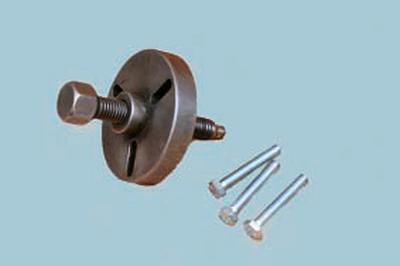
To remove the pressure plate, use a special puller.
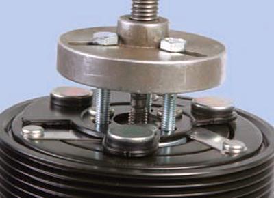
Screw the puller bolts into the threaded holes of the pressure plate and, by turning the stop screw of the puller, press the plate.
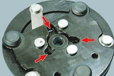
Sometimes the holes may not have threads. In this case, cut M5 or M6 threads in the holes yourself.
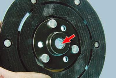
5. Inspect the splines of the pressure plate.
If the splines are worn, replace the plate.
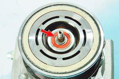
6. Inspect the shaft seal surface.
If there are signs of oil leakage through the shaft seal, the compressor must be replaced.
USEFUL TIP: In some cases, when a leak is detected, the seal can be replaced. However, it should be remembered that the leak is usually caused by shaft play due to wear of the support bearings, corrosion or wear of the shaft surface in the seal contact area. Therefore, replacing the seal will only provide a short-term result at best.
If a seal leak is detected, it is recommended to replace the compressor assembly.
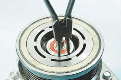
7. Using a special puller, squeeze…
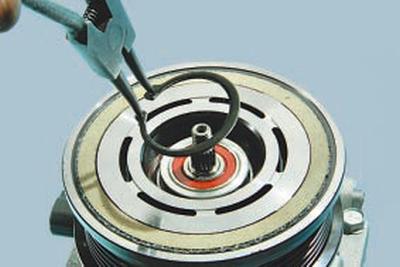
8….and remove the pulley bearing retaining ring.
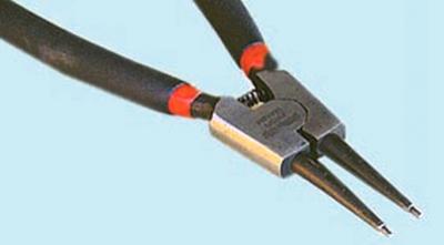
NOTE: Use a special snap ring expander to remove the snap ring.
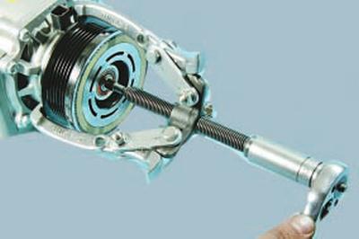
9. Install the three-jaw puller…
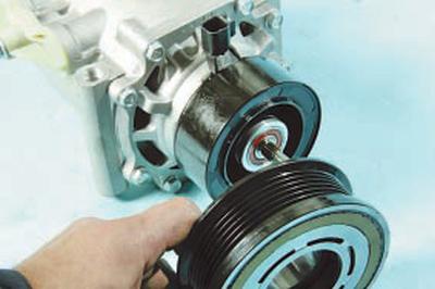
10….and press the pulley off the mounting neck of the compressor front cover.

USEFUL TIP: To remove the pulley, it is convenient to use a universal three-jaw puller.
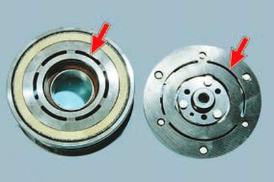
11. Inspect the working friction surfaces of the pulley and pressure plate, paying attention to the presence of deep scratches, burrs, obvious signs of wear and overheating. Replace defective parts if necessary.
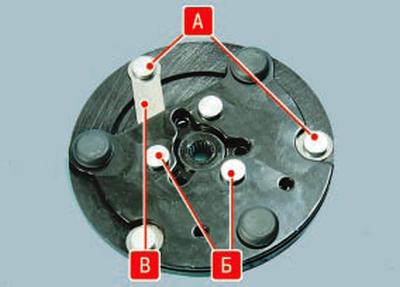
NOTE: Inspect the rivet joints A and B and the elastic steel lugs B of the plate. If the lugs are broken or the rivet joints are loose, replace the pressure plate.
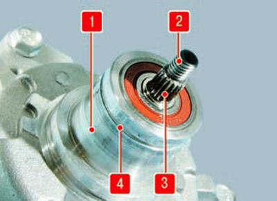
12. After removing the pulley, inspect the splines 3 and threaded end 2 of the shaft, groove 4 for the retaining ring and the seating surface 1 of the cover neck (the magnet coil has been removed for clarity). If they are worn or damaged, the compressor must be replaced.
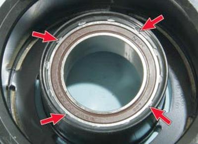
13. On a lathe, cut off the crimps that secure the bearing to the pulley.
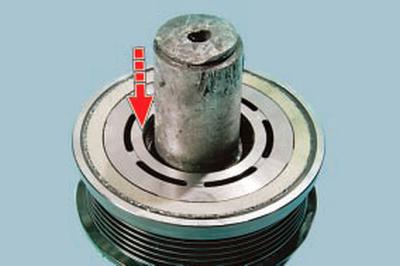
14. Using a mandrel of suitable diameter, press the old bearing out of the pulley.
WARNING: Once removed, the bearing is not suitable for reuse and must be replaced.
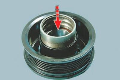
15. Press in the new bearing. When pressing in, apply force only to the outer race of the bearing. The race from the old bearing can be used as a mandrel.
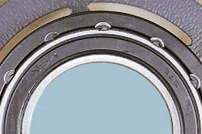
16. After pressing in, secure the bearing by punching the edge of the pulley mounting hole.
WARNING: Use extreme caution when pressing in the bearing.
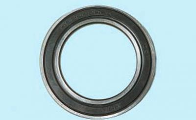
The outer race of the pulley bearing has a very thin wall. Even a slight tilt can cause the bearing to fail. After pressing, check the condition of the bearing. It should rotate evenly, silently, without jamming. There should be no axial or radial play.
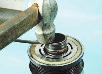
17. Press the pulley onto the compressor front cover. When pressing, apply force only to the inner bearing race.
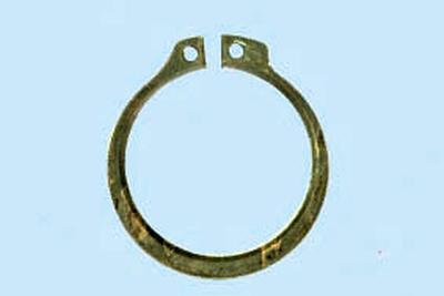
18. Install the retaining ring.
WARNING: After installing the pulley on the compressor, make sure that the pulley rotates smoothly, quietly, without jamming. There should be no axial or radial runout. Otherwise, the pulley must be replaced.
19. Place the pressure plate on the shaft and screw on the locking nut. Tighten the nut to a torque of 13 N·m.
20. Place the compressor in a vice.
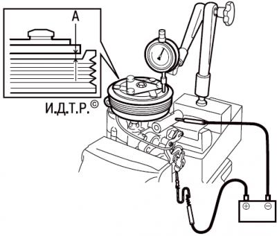
21. Install the dial indicator as shown in the figure. Connect the positive battery terminal to the coil winding connector and the negative battery terminal to the compressor housing. Measure the gap A between the friction surfaces of the pressure plate and the pulley (the gap value is equal to the measured difference between the engaged and disengaged air conditioner compressor clutch) every 60° around the circumference. If the gap is not the same at different points around the circumference, the pressure plate is deformed and must be replaced. The nominal gap is 0.35–0.85 mm.
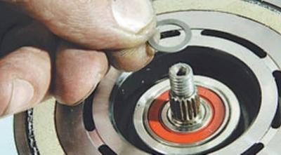
22. If the clearance differs from the nominal, remove the pressure plate. Using the adjusting washers installed on the rotor shaft, adjust the clearance. Put the pressure plate back on and check the resulting clearance.
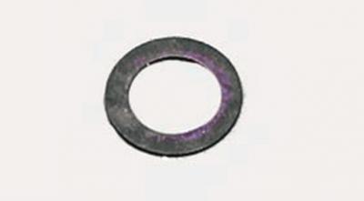
NOTE: Use special calibrated adjusting washers to adjust the clearance.
23. Install the compressor and all removed parts in the reverse order of removal.
24. Fill the air conditioning system with refrigerant at a specialized center for servicing automotive air conditioners.