Remove the front wheels.
Loosen the center axle shaft mounting nuts.
Lock the front wheels with the main (foot) brake and unscrew the axle nuts.
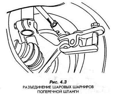
Disconnect the outer ends of the cross rods from the shoulders of the steering knuckles (Fig. 4.3).
Unscrew the elastic brake hose brackets from the suspension columns.
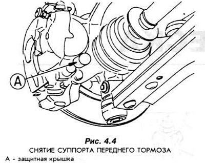
Remove the brake calipers by unscrewing the bolts from the mountings to the steering knuckles (Fig. 4.4).
Hang the removed calipers on a wire.
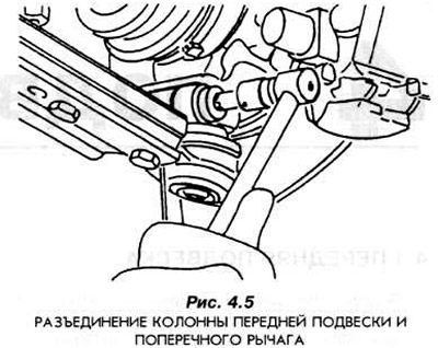
Disconnect the ball joints of the suspension column support on the wishbones (Fig. 4.5).
Unscrew the bolts and remove the brake discs.
Remove the steering knuckles and secure them one by one in a vice. Hang the free ends of the axle shaft on a wire.
Remove the axle shaft flange using puller 14-036.
Using a rod, knock the bearings out of the hub.
Wash the hub.
Special tools are required to install bearings.
After installing the bearing, the positions of the inner ring and radial seal must not be changed.
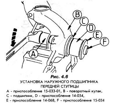
To install the outer bearing, it is necessary to use the 15-033-01 device (Fig. 4.6).
The inner bearing must be installed as shown in Fig. 4.7.
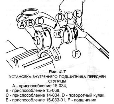
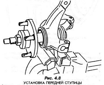
The hub is seated as shown in Fig. 4.8 using tools 15-033-01, 15-068 and 15-034.
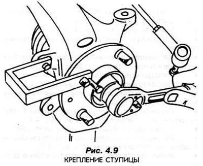
After removing the above mentioned devices, the hub must be immediately locked using device 14-036 (Fig. 4.9).
Further assembly of the unit is carried out in the reverse order of dismantling the hub. During assembly, it is necessary to strictly adhere to the recommended tightening torques of bolts and nuts.