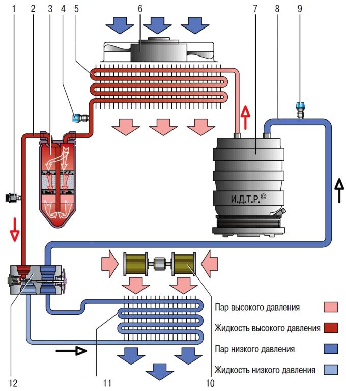
Pic. 12.2. Schematic diagram of the movement of the refrigerant in the air conditioning system: 1 - combined pressure sensor; 2 - section of the high pressure pipeline; 3 - receiver-drier; 4 - service valve of the high pressure line; 5 - condenser (air conditioning radiator); 6 - fan of the condenser and radiator of the cooling system; 7 - air conditioner compressor; 8 - section of the low pressure pipeline; 9 - service valve of the low pressure line; 10 - heater fan; 11 - evaporator; 12 - thermostatic valve.
Ford Mondeo cars are equipped with a compressor-type air conditioning system. The heater units and the air conditioner evaporator heat exchanger are made in one block. The controls for the air conditioning system are located on a panel shared with the heater controls.
A schematic diagram of the movement of the refrigerant in the air conditioning system is shown in fig. 12.2.
The compressor is mounted on the engine and driven by a V-ribbed belt.
NOTE: On vehicles with 1.6L Duratec-16V Ti-VCT engines (110 and 125 HP); 2.0 L Duratec-NOT (145 HP); 2.3 L Duratec-NOT (161 HP); 1.8 L Duratorq-TDCi (100 and 125 HP); 2.0 L Duratorq-TDCi (140 HP) and 2.2 L Duratorq-TDCi (170 HP) compressors of the Visteon VS16 model are installed, and with engines of 2.5 l Duratec-VI5 (220 HP) – Zexel KC88 model compressors. Both models of compressors have a similar design and differ mainly in the shape and location of the mounting elements.
The compressor circulates the refrigerant in the system. The compressor shaft is mounted in an aluminum housing on two needle bearings and sealed on the side of the drive pulley with an oil seal.
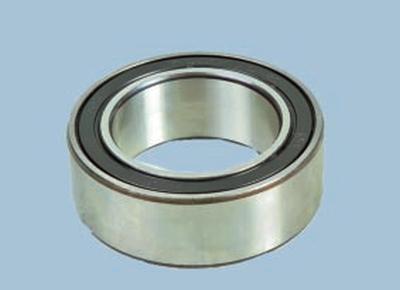
The compressor drive pulley is mounted on a double-row ball bearing and constantly rotates when the engine is running. When the air conditioner is turned on, torque is transmitted from the pulley to the compressor shaft through a friction clutch with an electromagnetic drive.
USEFUL ADVICE: When the air conditioner is turned on, a click is heard - this is the clutch, under the action of an electromagnet, engages with the drive pulley, and the compressor rotor begins to rotate.
This is if the system is working properly.
But during the operation of the air conditioner, several options for compressor malfunctions may occur.
1. If, when the air conditioner is turned off, the clutch makes extraneous sounds during rotation, heats up, or a burning smell appears, then its bearing has probably begun to collapse. In this case, the bearing must be replaced. In some advanced cases, it may be necessary to replace the compressor clutch or its constituent parts.
2. If there is no click after turning on the air conditioner, then it is possible: a - a refrigerant leak has occurred, and the electrical control circuit blocks the compressor from turning on; b - the pressure sensor in the system is out of order; c - the control circuit is broken; g - the coil of the electromagnetic clutch burned out; e - the engine control unit for some reason blocked the compressor from turning on.
3. If the clutch rotates easily and freely, but when the air conditioner is turned on, obvious extraneous noises are heard or the engine even stalls, then most likely the compressor is stuck. The internal pump part of the compressor cannot be repaired. In this case, the compressor will have to be replaced.
4. And the last, most unpleasant option. A click is heard, the clutch easily rotates the compressor shaft. There is no air cooling in the cabin. The compressor may be running idle.
In this case, only an experienced specialist in the presence of control and diagnostic equipment can determine the malfunction. If your car's compressor has been diagnosed «No compression», then you must be absolutely sure that it was installed by a good specialist. In case of doubt, you can re-diagnose and make sure that the considerable costs of purchasing and replacing the compressor are indeed inevitable.
In all these cases, an accurate answer about the cause of the malfunction can only be given by a complete diagnosis at a specialized service center for the repair of automobile air conditioners.
Condenser (air conditioning radiator) multi-flow type is located in front of the radiator of the engine cooling system.
It is attached using four supports installed in brackets on the radiator tanks.
The condenser cells are made of flat thin-walled aluminum tubes with internal longitudinal baffles for rigidity and external fins to improve heat transfer. Tanks are aluminum, with flanges for connection of tubes. The tanks are divided into sections along the height, therefore, passing through the condenser, the refrigerant flow changes direction several times. In the condenser, the vapors of the refrigerant compressed by the compressor are condensed and the heat released in this case is removed into the surrounding air.
When the air conditioner is turned on, the engine control unit turns on the power circuit for the additional electric fan of the engine cooling radiator. This improves the heat exchange in the condenser and reduces the pressure in the air conditioning system.
USEFUL ADVICE: At least once a year, preferably before the start of summer operation, wash the fins A of the condenser cells from adhering dirt, dust and anti-icing reagents B. This will improve heat transfer, reduce the pressure in the system and increase the service life of the system elements.
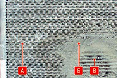
Do not use high pressure water jets to clean the condenser. This can damage the B thin-walled fins.
Even with regular washing, the need to replace the condenser occurs much more often than we would like. The fact is that he is the first to take on the flow of anti-icing reagents, dirt and pebbles from the road.
And his tubes are thin... In most cases, the condenser is damaged by corrosion in the third or fourth year of operation.
If, as a result of corrosion, the condenser has lost its tightness, then it is more expensive to repair it. Even if the master of argon welding manages to patch the hole, a leak may soon appear elsewhere. By the way, the pressure in the system on hot days can reach up to 25–30 atm.
In addition, it should be remembered that the condenser tube has a complex structure - along it is divided by partitions into channels. And it is highly likely that after welding, some of the channels will be blocked. Accordingly, the dissipated power will drop and the operation of the air conditioner will deteriorate, especially when standing in traffic jams and in hot weather.
Among other things, after each experiment with condenser welding, you will need to pay for welding, installation and dismantling of the condenser and charging the system with refrigerant. So it is better to install a new one right away, although instead of an expensive original one, it is quite possible to buy a cheaper condenser from authorized spare parts manufacturers.
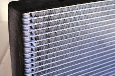
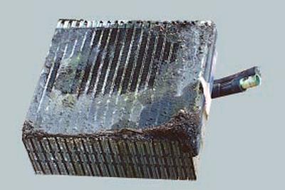
The evaporator is located in the heating and air conditioning unit. The evaporator is made of aluminum tubes with external fins to improve heat transfer.
Passing through the evaporator tubes, the boiling refrigerant actively absorbs heat from the air blowing over the outer finned surface of the tubes. The air is cooled and blown into the vehicle interior by a fan.
To prevent evaporator icing, some vehicles have an evaporator temperature sensor. This sensor measures the surface temperature of the evaporator fins. If the measured temperature drops below +2°C, the A/C compressor clutch is disengaged. If the temperature rises above +4°C, the compressor starts up again. The sensor signal on devices with manual temperature control is transmitted via the multifunctional electronic module (GEM) and a CAN bus to the engine control unit, which then engages or disengages the compressor clutch.
On devices with automatic temperature control, the sensor signal is first transmitted to the air conditioning control module and then via the CAN bus to the engine control unit, which then switches the compressor clutch on or off.
NOTE: When the air passing through the evaporator is cooled, the water vapor contained in it condenses. Condensate is drained through the drain tube under the bottom of the car. If the ambient humidity is high, a puddle of water may form under the car, which is an indirect sign of the health of the air conditioning system.
USEFUL ADVICE: During the operation of the car, particles of road dust and dirt settle on the outer surface of the evaporator that is wet from condensate.
This layer becomes an excellent environment for life and rapid reproduction of putrefactive bacteria and fungal cultures. Over time, an unpleasant odor develops in the car. It is especially strong when the air conditioner is turned off and in humid weather.
In order to minimize the risk of this problem, when buying a new car, it is necessary to carry out preventive treatment of the evaporator with special chemicals, regularly replace the cabin filter and clean the drain tube. If, despite the measures taken, the smell still appears, contact a specialized car air conditioning repair service to disinfect or flush the evaporator.
In case of very strong contamination, the evaporator will have to be replaced.
Access to the evaporator is on the right side of the climate unit. The evaporator can be removed and installed without removing the climate unit housing. To do this, you must first remove the heat exchanger (radiator) heater. When removing a factory-installed air conditioner evaporator, its connecting pipes must be cut. When repairing, an evaporator with separate removable pipelines is installed.
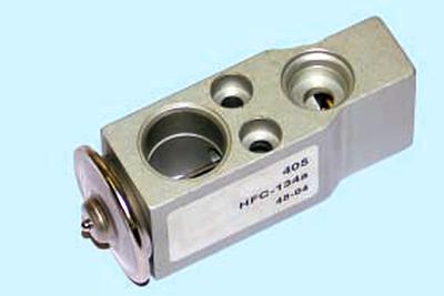
The block-type thermostatic expansion valve is located in the evaporator body. The valve is attached to pipelines by means of flange connections. After passing through the throttling hole in the valve body, the liquid refrigerant rapidly reduces pressure and begins to boil. A regulating element is installed in the valve body, which changes the flow area of the throttling hole depending on the pressure and temperature of the refrigerant. The control element is set at the factory and cannot be adjusted during operation.
WARNING: If particles of aluminum or plastic are found in the throttle port of the valve, then the pump part of the compressor has collapsed. Replacing only the thermostatic valve in this case will not give a positive result. You will need to replace the compressor with flushing the system. This rather time-consuming procedure can only be performed in a specialized service center using special technological equipment.
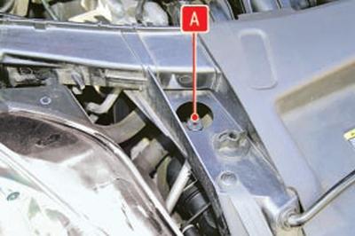
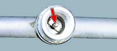
Receiver dryer 3 (see fig. 12.2) mounted on the condenser on the left side and forms a non-separable unit with it. The filter element is inside the housing (cartridge), filled with desiccant granules (silica gel). The liquefied refrigerant passing through the receiver is cleaned of possible impurities, dirt and moisture. The body of the receiver is made of aluminum alloy. In the lower part of the housing there is a hole for replacing the filter element.
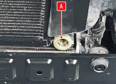
The hole is closed with a screw plug A with a sealing gasket.
WARNING: In case of repair or replacement of air conditioning system components, if it was in the open state (some units were removed, pipelines were destroyed, etc.), the receiver-dryer cartridge must be replaced. Otherwise, after charging the system, the refrigerant will not dry out and acids may form inside the system, which will destroy the parts of the air conditioner from the inside.
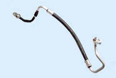
Piping connects all elements of the air conditioning system into a single hermetic circuit. Pipelines and their fastening flanges are made of aluminum alloys.
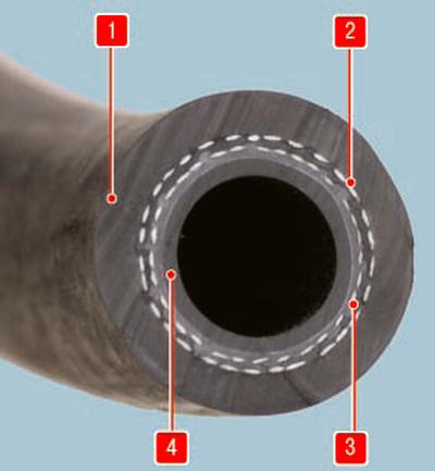
Pic. 12.3. The design of the hose of the flexible insert: 1 - outer protective sheath; 2 - fabric cord of the power frame; 3 - plastic sealing layer; 4 - inner oil-resistant layer
To connect the mutually moving elements of the system, pipelines in some sections have flexible inserts (pic. 12.3) from synthetic materials.
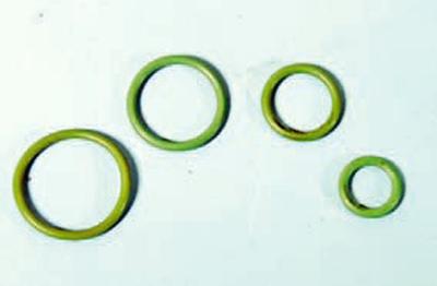
O-rings made of neoprene are installed at the joints of the individual elements of the system. During the repair of the system, when disconnecting sections of pipelines, sealing rings must be replaced. Tighten threaded pipe connections to the recommended torque. Weak or excessively strong tightening leads to deformation of the sealing surfaces and refrigerant leakage.
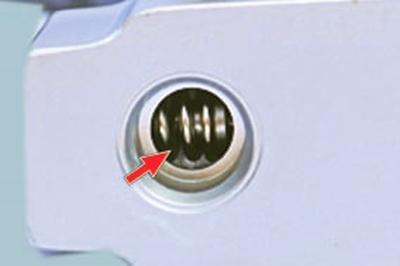
Two service valves for connecting diagnostic and filling equipment are located on the pipelines.
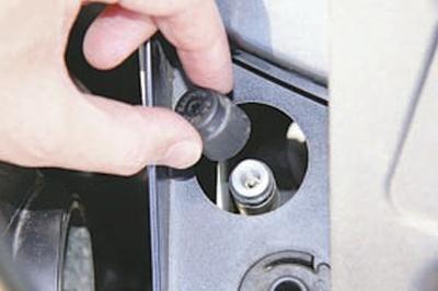
The valves are closed with threaded caps to protect them from dirt.
NOTE: This is how the service valves of the high A lines are located on the pipelines..
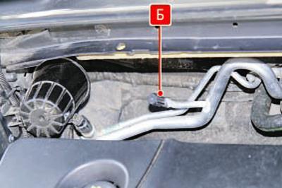
…and low B pressure.
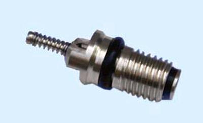
The valves are equipped with spools, similar in design to the spools of the wheel tires, but differing from them in size.
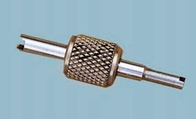
A special key is used to turn the spools in and out.
WARNING: It is forbidden to check the presence of refrigerant in the system by pressing the spools of the service valves, since after such a check the valve spool may not close completely and the refrigerant will leak from the system!
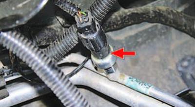
Pressure transmitter is installed in the pipeline section of the high pressure line. According to the sensor signals, the electronic engine control unit forcibly turns off the air conditioning compressor in case of depressurization of the system or an emergency increase in pressure in it in order to protect the compressor from overloads.
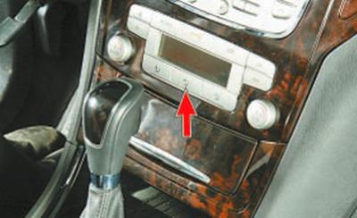
Manual or automatic block panel (depending on configuration) control of the ventilation, heating and air conditioning system is installed on the instrument panel console.
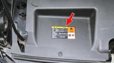
Refrigerant. An information plate indicating the type and amount of refrigerant used in the system is glued to the surface of the upper casing of the radiator lining.
It is strictly forbidden to use other types of refrigerants in the system. Special oil added to the refrigerant (PAG) for compressor lubrication.
Filling volumes of the system, g
Refrigerant R134a:
with compressor Visteon VS16……….520±15
with compressor Zexel KC88………….590±15
Oil……………………………………………..200±10
NOTE: During the operation of a car air conditioner, situations periodically arise when maintenance of the air conditioning system or its repair is required. For this, modern diagnostic and repair equipment is used. The most common situation is the depressurization of the system and the release of refrigerant from it.
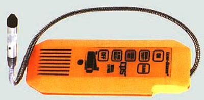
Highly sensitive halogen leak detectors with sound indication are used to detect leaks.
In some difficult cases, the so-called method is used. ultraviolet diagnostics of air-conditioning system tightness.
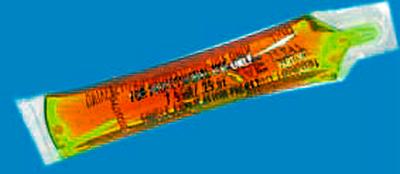
The method consists in the fact that a special dye is introduced into the system in microdoses.
In places of microflows, the dye, together with the refrigerant, gradually comes to the surface of the system elements.
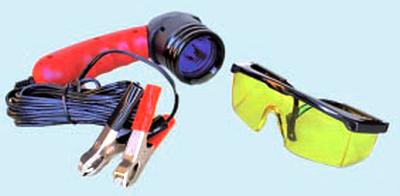
During the inspection of the system under the influence of ultraviolet rays of a special lamp, the dye begins to glow (fluoresce) …
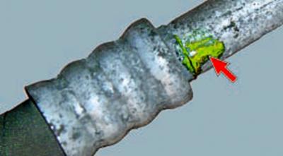
…and refrigerant leaks become visible.
It should be noted that the dye does not have any negative effect on the system. It can be in the refrigerant and circulate through the system for an arbitrarily long time and serve its purpose only when a leak occurs.
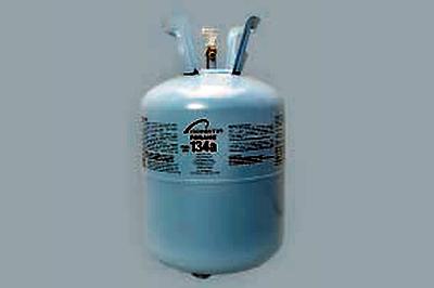
After repairing the air conditioner, it is necessary to evacuate and charge the system with the appropriate refrigerant (R134a).
The volume of refueling of the car air conditioner for each car model is individual.
To carry out high-quality refueling of a car air conditioner, you need:
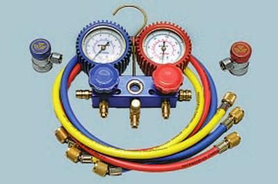
– precision manometric blocks with special connecting tips;
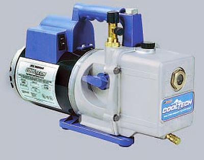
– two-stage vacuum pump for complete removal of air and water vapor from the system;
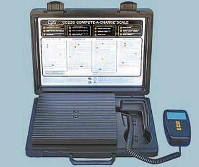
– high-precision (graduation value±5 g) scales for dosing the amount of charged refrigerant.
Due to the specific features of the repair of the air conditioning system, this section describes only the work on the removal and installation of individual elements and the system control unit. Work related to charging the system with refrigerant should be carried out in specialized service centers.
WARNING: The air conditioning system is charged with high pressure refrigerant. Contact of liquid refrigerant on human skin causes severe frostbite, so all work related to maintenance, repair or dismantling of air conditioning system elements should be carried out, if possible, in specialized service centers equipped with professional technological equipment. When working on your own, take precautions.
Visitor comments