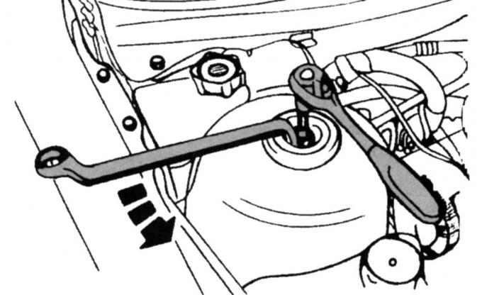
Fig. 118. Loosening the shock absorber strut mount
- loosen the nut in the middle of the piston rod by five turns (see Fig. 118);
- loosen the wheel nuts and wheel hub nuts and place the front of the vehicle on supports;
- remove the wheel;
- unscrew the fastening element of the trim from the inside of the wheel arch (four fastening points);
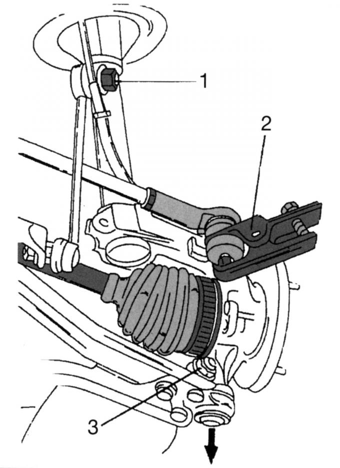
Fig. 175. Removing the right wheel drive shaft: 1 — anti-roll bar linkage and lever system; 2 - Tie rod end puller; 3 — suspension wishbone pivot clamping screw
- disconnect the system of rods and levers of the anti-roll bar from the shock absorber strut 1 (Fig. 175) of the chassis;
- press the head of the transverse steering rod with a puller;
- unscrew the clamping screw 3 of the suspension arm bolt;
- press the transverse lever down so that the connection is open;
- disconnect the lower part of the independent suspension wishbone from the wheel suspension;
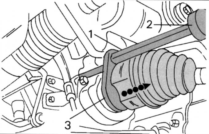
Fig. 176. Removing the right wheel drive shaft from the intermediate bearing using a special tool: 1 — tension plate joint bolt; 2 - the tension plate is installed under the constant velocity joint; 3 - hammer
- install a hammer with a removable plate (Fig. 176). Hit with hammer 3 until the shaft disengages from the intermediate bearing;
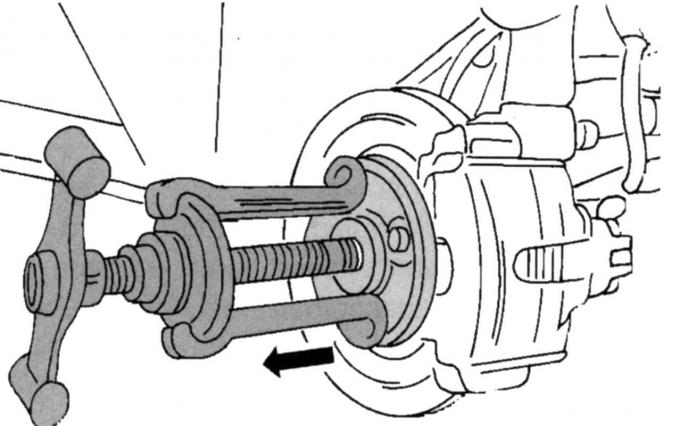
Fig. 177. Position of the puller on the wheel hub flange
- install the puller (Fig. 177);
- press the shaft out of the wheel hub.
Notes
- Do not create an internal hinge angle greater than 18°, or an external hinge angle greater than 45°
- All self-locking nuts and cut cable ties must be replaced with new ones.
To install the drive shaft, you must do the following:
- insert the shaft into the intermediate bearing and push it inwards - the retaining ring should snap into place;
- Pull the steering knuckle out as far as possible and insert the end of the shaft into the steering knuckle;
- Put the wheel hub on the outside;
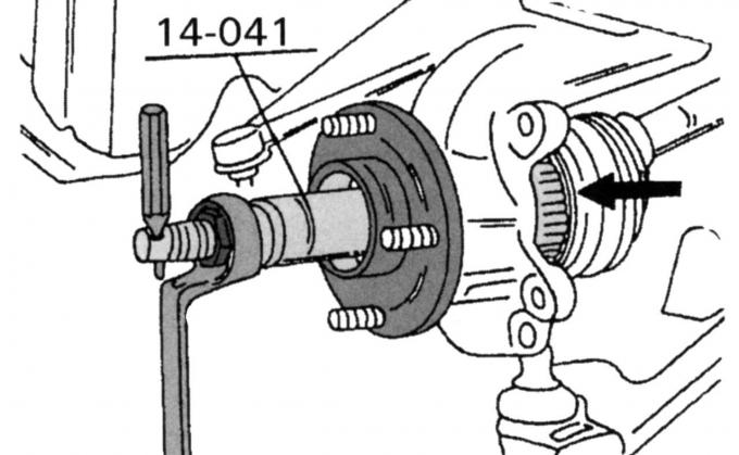
Fig. 178. Pressing in the drive shaft with a special tool
- press the wheel hub into the steering knuckle using the tool (Fig. 178);
- screw the nut onto the shaft and tighten it so that the shaft protrudes far enough to allow the hub to be put on;
- screw the nut on by hand;
- install the wishbone pivot into the steering knuckle, insert the bolt and tighten the connection to 83 Nm;
- attach the steering linkage rod to the steering knuckle (the bolt must be degreased);
- tighten the nut to a torque of 30 Nm;
- attach the anti-roll bar;
- tighten the connection on the shock absorber strut to a torque of 47 Nm;
- secure the wheel and lower the car onto its wheels;
- tighten the wheel nuts to 85 Nm and the shaft nut to 340 Nm;
- tighten the nut of the piston rod of the chassis shock absorber strut to a torque of 46 N·m;
- check and, if necessary, top up the oil level in the gearbox.
[The original source of this article can be found at: FordBook]