


To disassemble the wheel drive, the following operations must be performed:
- clamp the shaft in a vice, cut the clamping clamps of the cuffs and slide the sealing cuff onto the shaft;
- remove the three-pin joint. The rollers may fall out;
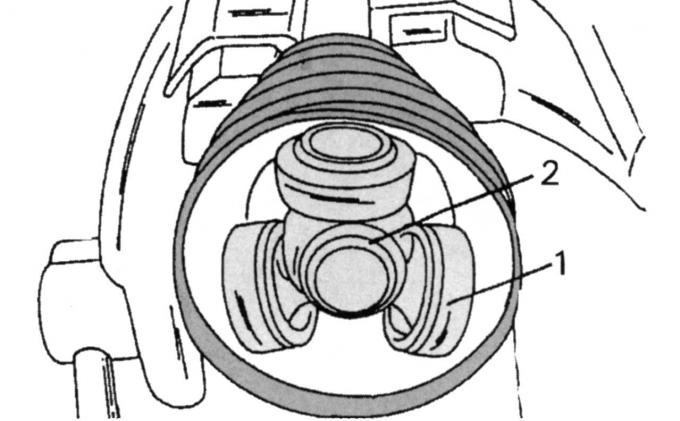
Fig. 180. Tripod type joint at the end of the shaft: 1 — support rollers; 2 - retaining ring
- remove the spring retaining ring 2 (Fig. 180) and remove the rollers from the journals. The articulated sprocket is pressed onto the shaft and must be removed with a suitable puller;
- remove the rubber cuff;
- cut and remove the clamps and slide the cuff back;
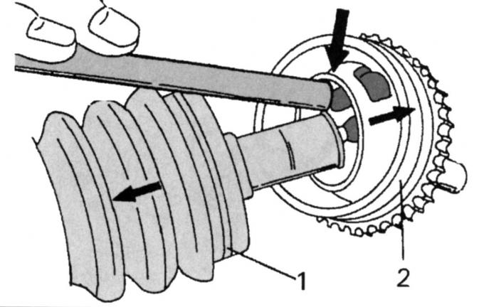
Fig. 181. Removing the joint from the shaft (direction indicated by the arrow): 1 — joint sealing cuff; 2 - axial joint with toothed rim
- Using a brass punch or similar tool (Fig. 181), strike the joint briefly. This will cause the snap ring to pop out of the groove. Do not damage the bearing;
- pull the joint off the shaft, remove the retaining ring from the groove (it can no longer be used) and remove the sealing cuff.
Further disassembly is not possible.
Before assembly, clean all parts and replace with new ones if necessary.
When installing the drive side joint, proceed as follows:
- install the cuff on the drive side and secure with a small clamp;
- press the joint sprocket until it stops on the shaft using a special mandrel (you can use a piece of pipe). At the same time, do not allow the sliding journals on the rollers to slip or be damaged;
- install a new snap ring into the groove;
- lubricate the rollers with consistent grease and fit them onto the main journals;
- lubricate the three-pin joint;
- insert a small screwdriver between the cuff and the hinge to remove air, press the three-pin hinge until it stops inward and then pull it out by about 20 mm;
Note: When using a screwdriver, be careful not to pierce the cuff.
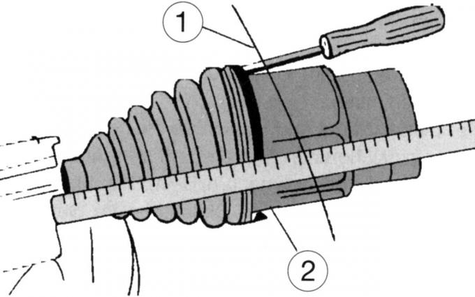
Fig. 182. Installing the rubber seal on the drive side
- install the cuff on the hinge (Fig. 182);
- remove the screwdriver and secure the cuff on the shaft.
When installing the joint from the wheel side, proceed as follows:
- loosely place a small clamp on the cuff and slide the cuff onto the shaft;
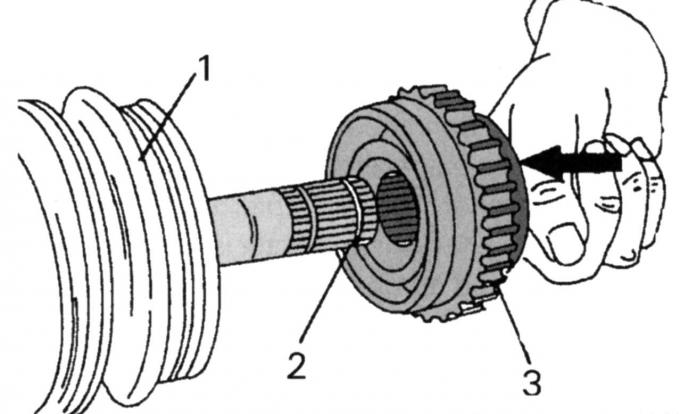
Fig. 183. Assembling the joint from the wheel side: 1 — cuff; 2 - spring retaining ring; 3 - axial hinge
- replace the spring retaining ring 2 with a new one (Fig. 183). Leave the second ring on the shaft;
- check the reliability of the installation of the retaining ring and fill the joint with exactly 100 g of the recommended lubricant;
- push both halves of the drive shaft together so that the retaining ring is fixed on the inside;
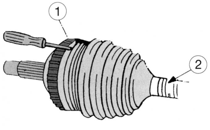
Fig. 184. Installing the rubber cuff
- insert the cuff into the groove of the drive shaft, insert the screwdriver again between the cuff and the joint and squeeze the cuff, while removing the screwdriver (Fig. 184);
- tighten the cuff clamp.
[The text is available on the specified website info portal FORDBOOK.ru]