- unscrew the wheel nuts;
- jack up the front of the car;
- remove the wheels;
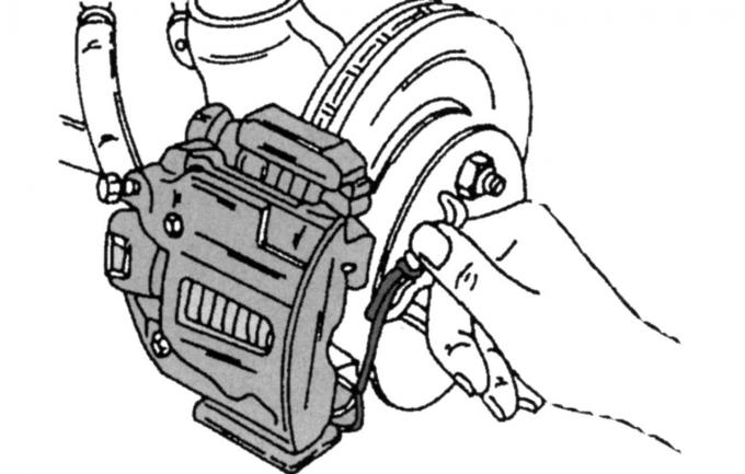
Fig. 251. Brake shoe safety clamp
- remove the safety clip from the brake caliper (Fig. 251);
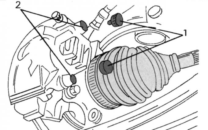
Fig. 252. Brake caliper mounting: 1 — protective caps; 2 - bolts
- remove both protective caps 1 (Fig. 252) from the bolts 2 securing the brake caliper;
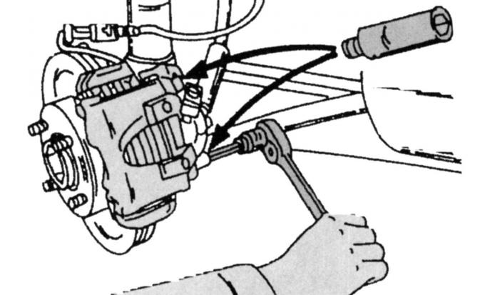
Fig. 253. Removing the brake caliper
- using a 7 mm Allen key, unscrew both bolts 2, as shown in Fig. 253, so that the cylinder body can be freely removed from the caliper holder;
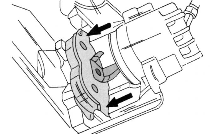
Fig. 254. Removing the outer brake shoe
- unscrew the cylinder body and the caliper from the caliper holder and remove both pads, for which first remove the inner pad, then press the second pad away from the piston until it is installed in the position shown in Fig. 254, now it can be removed;
Note: Use Ford brake pads or Ford approved parts when assembling.
Install the brake pad in the reverse order of removal, taking into account the following:
- be sure to check that the brake pad installed is approved by the manufacturer, there should be no grease on the surface of the pad and the brake disc;
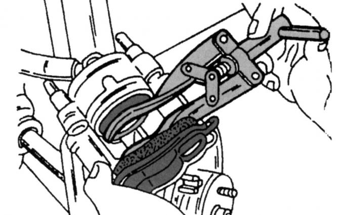
Fig. 255. Recessing the brake caliper piston
- be sure to recess the piston if new pads are installed; if the master cylinder expansion tank is full, this may cause the tank to overflow and leak fluid, in this case, use a rubber bulb to pump out some fluid from the tank. To press the piston, use a mounting blade or a special collet, which is shown in Fig. 255; if brake fluid gets on the car's paintwork, wash it off immediately with cold water;
- remove the paper from the new pad, insert the inner pad into the cylinder body and the outer pad into the caliper holder and piston;
- install the body on the caliper holder;
- screw in both bolts shown in Fig. 253 and tighten with a 7 mm Allen key to a torque of 28 N·m, then insert the shut-off plugs into the holes;
- perform the remaining installation operations in the reverse order of removal;
- check the fluid level in the tank;
- press the brake pedal several times to allow the brake pads to rub against the brake discs.